


SCHOTTKY BIPOLAR
8214
Control Signals
The
8214
also has several inputs
that
enable
the
designer
to
synchronize
the
interrupt
issued
to
the
microprocessor and
to
allow
or
disallow such an issuance. Also, signals are pro-
vided
that
perm
it
simple expansion
to
other
8214s
so
that
more
than
eight levels can be controlled.
INTE,
elK
The
INTE
(Interrupt
Enable)
input
allows
the
designer
to
"shutoff"
the
interrupt
system
under
control
of
external
logic
or
possibly
under
software maintenance. A
"zero"
on
this line will
not
allow
interrupts
to
be issued
to
the
micro-
computer
system.
The
ClK
(Clock)
input
is
actually
the
trigger
that
strobes
the
Interrupt
Flip-Flop.
It
can be
connected
to
one
of
the
clocks
of
the
microprocessor so
that
the
interrupt
issued
meets
the
CPU set-up
time
specification. Note
that
due
to
the
gating
of
the
input
to
the
I
nterrupt
Flip-Flop
the
I
NT
output
will only be active
for
the
time
of
a single clock pe-
riod, so external latching may
be
required
to
hold this
sig-
nal.
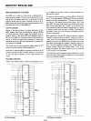
ElR,
ETlG,
ENGl
These
three
signals allow
8214s
to
be cascaded so
that
more
than eight levels
of
interrupt
requests can be controlled.
Basically,
the
ENLG
output
of
one
8214
is
connected
to
the
ETLG
input
of
the
next
and so
on,
with
the
first
8214
having its ETLG
input
pulled
"high"
and assigned
the
high-
est priority. When
the
ENlG
output
is
"high"
it indicates
that
there
is
no
interrupt
pending on
that
device and
that
interrupts can
be
monitored
on
the
next
lower priority
8214.
This
"cascading"
can be expanded almost indefinitely
to
accomodate even
the
largest
of
interrupt
driven system
architectures.
AO,
A1,
A2
In
order
to
identify which device has interrupted
the
pro-
cessor so
that
the
service routine associated
with
it can be
addressed, a
pointer
or
"vector"
must
accompany
the
inter-
rupt
issued
to
the
microcomputer
system.
The
AD,
A1 and A2
outputs
represent
the
complement
of
the
active
interrupt
level (modulo 8).
By
using these signals
to
encode
the
special instruction, RST,
the
program
counter
of
the
microprocessor, can
point
to
the
location
of
the
service routine. Note
that
these
three
outputs
are gated by
the
ELR
input
and are open collector so
that
expansion
is
simplified.
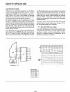
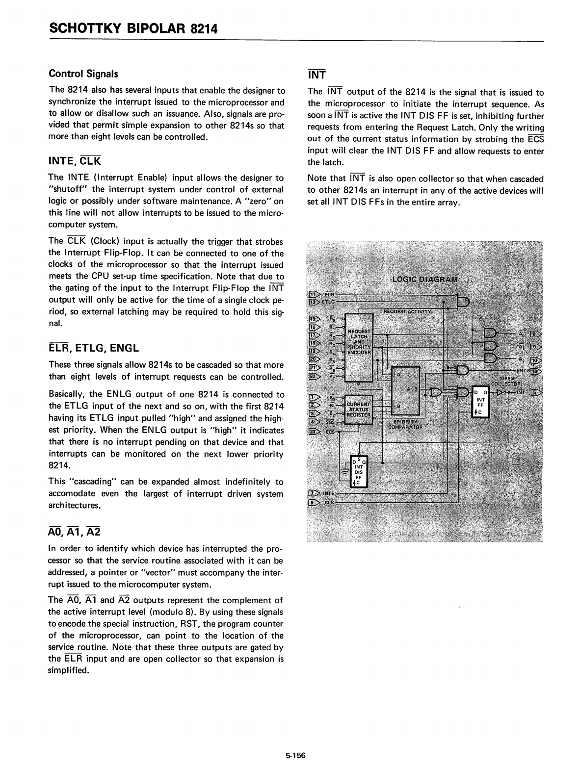
INT
The
INT
output
of
the
8214
is
the
signal
that
is issued
to
the
microprocessor
to
initiate
the
interrupt
sequence.
As
soon a INT
is
active
the
INT DIS
FF
is
set, inhibiting
further
requests from entering
the
Request Latch. Only
the
writing
out
of
the
current
status
information by strobing
the
ECS
input
will clear
the
INT DIS FF and allow requests
to
enter
the
latch.
Note
that
INT
is
also
open
collector
so
that
when
cascaded
to
other
8214s
an
interrupt
in
any
of
the
active devices will
set
alllNT
DIS FFs
in
the
entire
array.
5-156