


SILICON GATE MOS
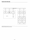
8251
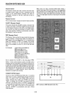
Modem Control
The
8251 has a
set
of
control
inputs
and
outputs
that
can
be used
to
simplify
the
interface
to
almost
any
Modem.
The
modem
control
signals are general
purpose
in
nature
and can be used
for
functions
other
than
Modem
control,
if necessary.
DSR
(Data Set Ready)
The
DSR
input
signal
is
general
purpose
in
nature. Its con-
dition can be tested
by
the
CPU using a
Status
Read opera-
tion.
The
DSR
input
is
normally used
to
test
Modem con-
ditions such as Data
Set
Ready.
DTR (Data Termin·al Ready)
The
DTR
output
signal
is
general
purpose
in
nature. It can
be
set
"low"
by programming
the
appropriate
bit
in
the
Command Instruction word.
The
DTR
output
signal
is
norm-
ally used for Modem
control
such as Data Terminal Ready
or
Rate Select.
RTS
(Request
to
Send)
The
RTS
output
signal
is
general
purpose
in nature. It can
be set
"low"
by
programr:ning
the
appropriate
bit
in
the
Command Instruction word.
The
RTS
output
signal
is
norm-
ally used
for
Modem
control
such as
Request
to
Send.
CTS
(Clear
to
Send)
A
"low"
on this
input
enables
the
8251
to
transmit
data
(serial) if
the
Tx
EN
bit
in
the
Command
byte
is
set
to
a
"
one
."
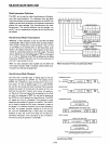
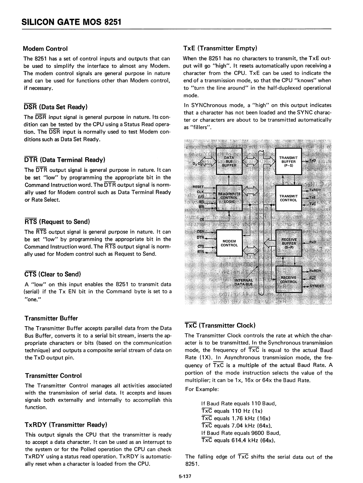
Transmitter Buffer
The
Transmitter
Buffer accepts parallel
data
from
the
Data
Bus Buffer, converts it
to
a serial
bit
stream,
inserts
the
ap-
propriate characters
or
bits (based
on
the
'communication
technique) and
outputs
a
composite
serial stream
of
data
on
the
TxD
output
pin.
Transmitter Control
The
Transmitter
Control manages all activities associated
with
the
transmission
of
serial
data.
It accepts and issues
signals
both
externally
and internally
to
accomplish
this
function.
TxRDY
(Transmitter Ready)
This
output
signals
the
CPU
that
the
transmitter
is
ready
to
accept a
data
character~
It can be used as an
interrupt
to
the
system
or
for
the
Polled
operation
the
CPU can check
TxRDY
using a status read
operation.
TxRDY
is
automatic-
ally reset when a
character
is
loaded from
the
CPU.
TxE (Transmitter Empty)
When
the
8251 has no characters
to
transm
it,
the
TxE
out-
put
will go
"high".
It resets
automatically
upon
receiving a
character
from
the
CPU.
TxE
can be used
to
indicate
the
end
of
a transmission
mode,
so
that
the
CPU
"knows"
when
to
"turn
the
line
around"
in
the
half-duplexed operational
mode.
In
SYNChronous
mode,
a
"high"
on
this
output
indicates
that
a
character
has
not
been loaded and
the
SYNC charac-
ter
or
characters are
about
to
be
transmitted
automatically
as "fillers".
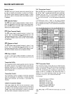
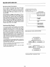
TxC (Transmitter Clock)
The
Transmitter
Clock
controls
the
rate
at
which
the
char-
acter
is
to
be
transmitted.
In
the
Synchronous
transmission
mode,
the
frequency
of
TxC
is
equal
to
the
actual Baud
Rate
(1
X).
In
Asynchronous
transmission
mode,
the
fre-
quency
of
TxC
is
a
multiple
of
the
actual Baud Rate. A
portion
of
the
mode
instruction
selects
the
value
of
the
multiplier; it can be 1x,
16x
or
64x
the
Baud Rate.
For
Example:
If
Baud Rate equals
110
Baud,
TxC
equals
110
Hz (1x)
TxC
equals
1.76
kHz (16x)
TxC
equals
7.04
kHz (64x).
If Baud Rate equals
9600
Baud,
TxC
equals
614.4
kHz (64x).
The
falling edge
of
TxC
shifts
the
serial
data
out
of
the
8251.
5-137