


118
CHAPTER 5 TIME-BASE TIMER
5.2 Configuration of Time-base Timer
The time-base timer consists of the following four function blocks.
• Time-base counter
• Counter clear circuit
• Interval timer selector
• Time-base timer control register (TBTC)
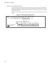
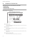
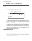
■ Block Diagram of Time-base Timer
Figure 5.2-1 Block Diagram of Time-base Timer
● Time-base timer counter
A 21-bit up counter that accepts the oscillation frequency divided by two as the count clock and stops
operating when oscillation stops.
● Counter clear circuit
Clears the counter when the TBTC register is set (TBR = 0), stop mode is entered (STBC: STP = 1), or a
power-on reset occurs.
● Interval timer selector
Selects 1 bit for the interval timer from four bits in the time-base counter. When the specified bit overflows,
an interrupt occurs.
● Time-base timer control register (TBTC)
Selects a time interval, clears the counter, controls interrupts, or checks the status.
TB0F TBIE TBC1 TBC0 TBR
OF
OF
OF
OF
F
CH
: Oscillation frequency
X2
1
Time-base timer counter
X2
2
X2
3
X2
6
X2
7
X2
8
X2
9
X2
10
X2
11
X2
12
X2
13
X2
14
X2
15
X2
16
X2
17
X2
20
X2
21
To A/D converter
To watchdog timer
F
CH
divided
by two
Clearing counter
To clock control
section oscillation
stabilization time
selector
Clearing watchdog timer
Power-on reset
Starting stop mode
(in normal mode)
Counter
clear
circuit
Interval timer
selector
IRQ7 (time-base timer interrupt)
OF: Overflow
Time-base timer control register (TBTC)