


245
CHAPTER 11 EXTERNAL INTERRUPT CIRCUIT 2 (LEVEL)
11.2 Configuration of External Interrupt Circuit 2
The external interrupt circuit 2 comprises the following three blocks:
• Interrupt request generating circuit
• External interrupt 2 control register (EIE2)
• External interrupt 2 flag register (EIF2)
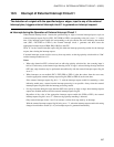
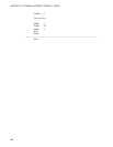
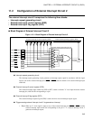
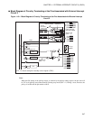
■ Block Diagram of External Interrupt Circuit 2
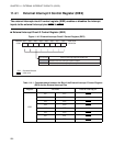
Figure 11.2-1 Block Diagram of External Interrupt Circuit 2
● Interrupt request generating circuit
The interrupt request generating circuit generates an interrupt request signal in accordance with the signal
input to one of the external interrupt pins (INT20
to INT27) and the contents of an external interrupt input
enable bit.
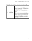
● External interrupt 2 control register (EIE2)
The external interrupt input enable bits (IE20 to IE27) enable or disable "L" level input from the external
interrupt pins, with each bit corresponding to a pin.
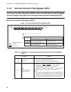
● External interrupt 2 flag register (EIF2)
The external interrupt request flag bit (IF20) is used to hold or clear an interrupt request signal.
● Trigger causing external interrupt circuit 2 to generate an interrupt
• IRQA:When an "L" level signal is input to any of the external interrupt pins INT20
to INT27 and the
external interrupt input enable bit corresponding to the pin is "1", external interrupt circuit 2
generates an interrupt request.
IE27 IE26 IE25 IE24 IE23 IE22 IE21
IE20
IF20
IRQA
P00/INT20/AN4
P01/INT21/AN5
P02/INT22/AN6
P03/INT23/AN7
P04/INT24
P05/INT25
P06/INT26
P07/ INT27
Pin
Pin
Pin
Pin
Pin
Pin
Pin
Pin
External interrupt 2 control register (EIE2) External interrupt 2 flag register (EIF2)
Interrupt request generating circuit
External interrupt
request