


284
CHAPTER 13 UART
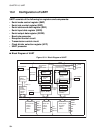
13.2 Configuration of UART
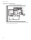
UART consists of the following ten registers and components:
• Serial mode control register (SMC)
• Serial rate control register (SRC)
• Serial status and data register (SSD)
• Serial input data register (SIDR)
• Serial output data register (SODR)
• Baud rate generator
• Reception control circuit
• Transmission control circuit
• Clock divider selection register (UPC)
• UART prescaler
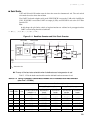
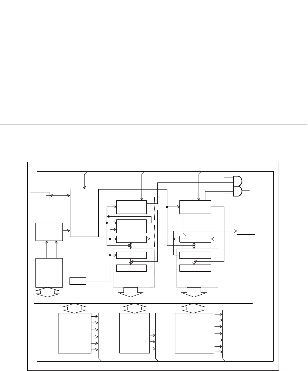
■ Block Diagram of UART
Figure 13.2-1 Block Diagram of UART
PEN
SBL
MC1/0
SMDE
SCKE
SOE
RDRF
ORFE
TDREX
TIE
RIE
TP
RP
CR
CS1/0
RC2 to 0
P30/UCK/SCK
P31/UO/SO
P32/UI/SI
RIE
TIE
IRQ6
RP TP
IRQ5
PR2,1,0PREN
Control bus
Pin
Baud rate
generator
Transmission
clock
Reception control
circuit
Reception
interrupt
UART
interrupt
Transmission
control circuit
Transmission
interrupt
Received
byte
counter
Transmitted
byte counter
Start bit
detection
circuit
Parity
transmission
timing
UART
prescaler
Reception clock
Parity
Parity
Shift register
Shift register
Register
Register
Completion
of receipt of
one byte
<Serial input data
register (SIDR)>
<Serial output
data register
(SODR)>
Clock
divider
selection
register
(UPC)
Serial mode
control
register
(SMC)
Serial rate
control
register
(SRC)
Internal data bus
Serial status
and data
register
(SSD)
Control bus
Pin
Pin