


283
CHAPTER 13 UART
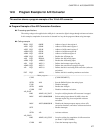
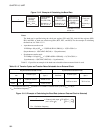
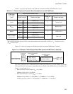
Table 13.1-4 provides an example of the baud rates selectable when the 8-bit PWM timer is used.
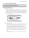
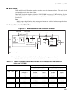
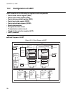
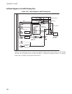
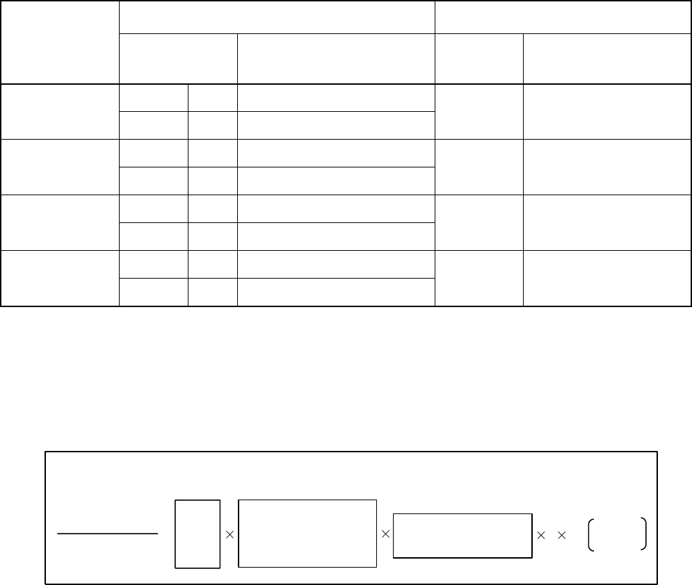
Figure 13.1-4 shows an example of calculating the baud rate when the PWM timer is selected.
Figure 13.1-4 Example of Calculating the Baud Rate (when the PWM Timer is Selected)
The value of the baud rate is determined by the clock input specified in the clock dividing rate register
(CS1 and CS0). The clock input is determined with an external clock (PWM timer). For calculation, see
Table 13.1-3 and Table 13.1-4 .
• When an external clock is selected (F
CH
= 12.5 MHz)
1/49kbps=1.28 µs (min.) × 16 (CR=0)
• When the PWM timer is selected (F
CH
= 12.5 MHz)
1/98kbps=0.32 µs (4/F
CH
) × 1 (P1=0,P0=0) × 1 (COMR=0) × 2 × 16 (CR=0)
1/24414 bps=0.32 µs (4/F
CH
) × 1 (P1=0,P0=0) × 1 (COMR=0) × 2 × 64 (CR=1)
Table 13.1-4 Transfer Cycles and Transfer Rates Selectable for the 8-bit PWM Timer
PWM timer
count clock
cycle
Asynchronous transfer mode Synchronous transfer mode
Divider for clock Transfer rate (bps)
Divider for
clock
Transfer rate (bps)
1t
INST
CR=0 16 97656 to 763
2 781k to 6.1k
CR=1 64 24414 to 191
16t
INST
CR=0 16 6103 to 47.8
2 48828 to 381.5
CR=1 64 1526 to 11.9
64t
INST
CR=0 16 1526 to 11.9
2 12207 to 95.4
CR=1 64 381.5 to 3
8/16-bit capture
timer/counter
CR=0 16 48828 to 381.5
2 391k to 3k
CR=1 64 12207 to 95.4
t
INST
: Instruction cycle
The system clock control register (SYCC) selects the maximum clock speed (CS1 and CS0 = 11
B
, 1 instruction cycle =
4/F
CH
) in active mode.
64/F
CH
16/F
CH
8/F
CH
4/F
CH
1(P1=0,P0=0)
16(P1=0,P0=1)
64(P1=1,P0=0)
8/16 timer (P1=1,P0=1)
=
2
CR
CR=0:16
CR=1:64
1
Value of baud rate
Clock gear
selected
Input clock select bit
(PWM)
Compare register
(COMP)
Value specified in the
compare register + 1