


290
CHAPTER 13 UART
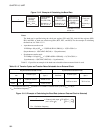
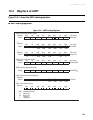
13.4.1 Serial Mode Control Register (SMC)
The serial mode control register (SMC) specifies the parity setting, stop bit length,
operating mode (data length), and synchronous/asynchronous mode, and enables/
disables UART serial clock output and serial data output.
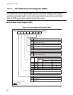
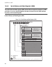
■ Serial Mode Control Register (SMC)
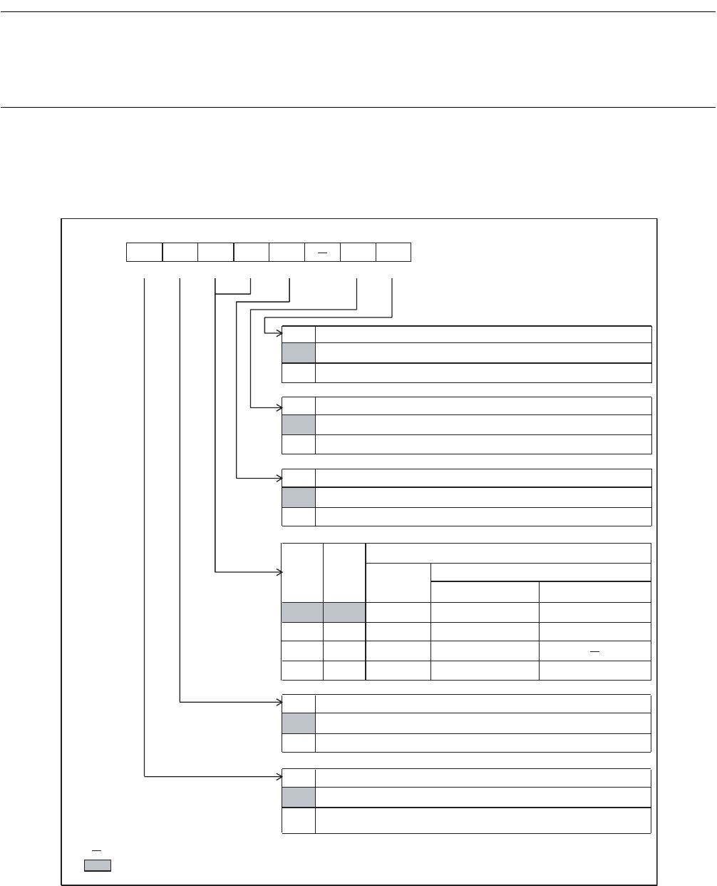
Figure 13.4-2 Serial Mode Control Register (SMC)
SOE
0
1
SCKE
0
1
SMDE
0
MC1 MC0
00 0 7 bits
6 bits
01 1 8 bits
7 bits
10 2 8+1 bits
11 3 9 bits8 bits
SBL
0
PEN
0
bit7 bit6 bit5 bit4 bit3bit2 bit1 bit0
0028
H
PEN SBL
MC1 MC0 SMDE
SCKE SOE
00000-00
B
R/W R/W R/W R/W R/W R/W R/W
R/W : Readable/Writable
: Unused
: Initial value
1
1
1
Address
Initial value
Serial data output enable bit
General-purpose port or 8-bit serial I/O data output pin
UART serial data output pin
Clock output enable bit
General-purpose port or clock input pin for UART/8-bit serial I/O
UART clock output pin
Synchronization mode selection bit
Synchronous transfer mode
Asynchronous transfer mode
Operating mode selection bits
Operating
mode
Data written:
Without parity
(PEN = 0)
With parity
(PEN = 1)
Stop bit length selection bit
2 bits
1 bit
Parity enable bit
Parity disabled
Parity enabled (TD8/TP in the SSD register allows choice of
even/odd.)