


316
CHAPTER 14 8-BIT SERIAL I/O
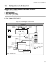
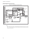
● Shift clock control circuit
As a shift clock of the shift clock control circuit, one of three internal clocks and one external clock is
selected.
Selecting an internal clock enables the shift clock to be output to the SCK pin. Selecting an external clock
enables the clock to be input from the SCK pin to act as the shift clock. The shift clock control circuit shifts
the SDR in accordance with this shift clock and outputs the shifted-out value to the SO pin. It also captures
the data input from the SI pin while shifting it to the SDR.
● Shift clock counter
The shift clock counter counts the number of times the SDR was shifted using the shift clock. When 8-bit
shift is completed, the counter overflows.
When the counter overflows, the serial I/O transfer start bit of the SMR (SST = 0) is cleared and the
interrupt request flag bit (SIOF = 1) is set. When serial transfer stops (SST = 0), the counter stops its count.
It is cleared when serial transfer is started (SST = 1).
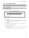
● Serial data register (SDR)
The SDR retains transfer data. The data written to the SDR is converted to serial data and output. Serial
input is converted to parallel data and stored.
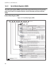
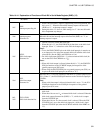
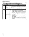
● Serial mode register (SMR)
The SMR is a serial I/O control register. It is used to allow and prohibit serial I/O operation, select shift
clocks, and set a transfer (shift) direction. It is also used to control interrupts and check interrupt states.
● 8-bit serial I/O interrupt
• IRQC:If the interrupt request output is allowed (SMR: SIOE = 1) when the I/O function of the 8-bit
serial I/O inputs or outputs 8-bit serial data, a interrupt request (IRQC) is generated.