


52
CHAPTER 3 CPU
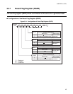
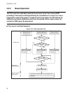
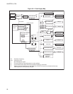
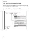
Figure 3.6-1 Clock Supply Map
F
CH
: Oscillation frequency
t
INST
*1
*2
*3
*4
UART
7
1t
INST
4
1t
INST
3
8
8
(*2)
(*1)
(*2)
(*2)
(*2)
(*1)
(*2)
X0 pin
Oscillation
circuit
F
CH
1/2
frequency
Time-base timer
Stop mode
Oscillation
control
1/4 frequency
1/8 frequency
1/16 frequency
1/64 frequency
Clock controller
Gears
Sleep, stop, oscillation
stabilization wait
Stop
Supplied to
CPU
Supplied to
peripheral circuits
Free-run counter
Watchdog timer
8/16-bit capture
timer/counter
EC pin
T0 pin
8-bit PWM timer
PWM pin
(*2)
3
4
(*1)
(*2)
(*2)
(*4)
A/D converter
AN pin
Continuous
conversion
Continuous
conversion
Conversion/
comparison
UART
prescaler
Serial switch
UCK/SCK pin
U0/S0 pin
UI/SI pin
8-bit serial I/O
Buzzer
BZ pin
12-bit PPG PPG pin
External interrupt 1
INT1 pin
External interrupt 2
INT2 pin
Oscillation
stabilization
wait time
: Instruction cycle
: Not affected by the gear.
: The gear affects the operating speed or other settings.
: The time-base timer stops when the oscillation frequency clock halts.
: Output of the time-base timer is selectable when the A/D converter is activated continuously.
Other operations are affected by the gear.
3
(*3)
X1 pin