


143
CHAPTER 7 8-BIT PWM TIMER
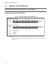
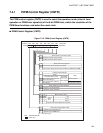
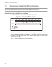
7.4.1 PWM Control Register (CNTR)
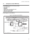
The PWM control register (CNTR) is used to select the operation mode (interval timer
operation or PWM timer operation) of the 8-bit PWM timer, switch the resolution of the
PWM timer functions, and select the count clock.
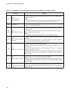
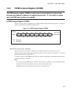
■ PWM Control Register (CNTR)
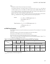
Figure 7.4-2 PWM Control Register (CNTR)
TIE
0
1
OE
0
1
TIR
0
1
TPE
0
1
P1 P0
0
0
1 t
INST
0
1
16 t
INST
10
64 t
INST
11
P/TX
0
1
t
INST
: Instruction cycle
bit7 bit6 bit5 bit4 bit3 bit2 bit1 bit0
0022
H
P/TX
P1 P0
TPE TIR OE TIE
0-000000
B
R/W R/W R/W R/W R/W R/W R/W
R/W
Address Initial value
Bit to enable an interrupt request
Disables interrupt request output.
Enables interrupt request output.
Bit to control the output pin
Used as the general-purpose port (P50)
Used as the output pin for the interval timer or PWM timer (PWM)
Interrupt request flag bit
Read
Write
The interval timer used
The PWM
timer used
The counter value does not
match the settings.
Not changed
Clears this bit.
The counter value matches
the settings.
Not changed. Does
not affect other settings.
Bit to enable the counter operation
Stops the counter operation.
Starts the counter operation.
Bits to select a clock
Internal
count
clock
Outputs an 8/16-bit capture timer/counter.
Bit to select the operation mode
Operates as the interval timer.
Operates as the PWM timer.
: Readable/Writable
: Initial value