


294
CHAPTER 13 UART
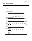
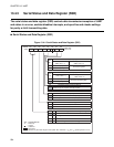
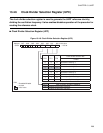
13.4.3 Serial Status and Data Register (SSD)
The serial status and data register (SSD) controls data transmission/reception of UART
and status in an error, enables/disables interrupts, and specifies and checks settings
for parity or bit-8 transmitting data.
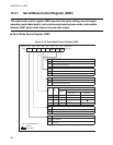
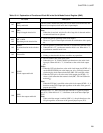
■ Serial Status and Data Register (SSD)
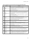
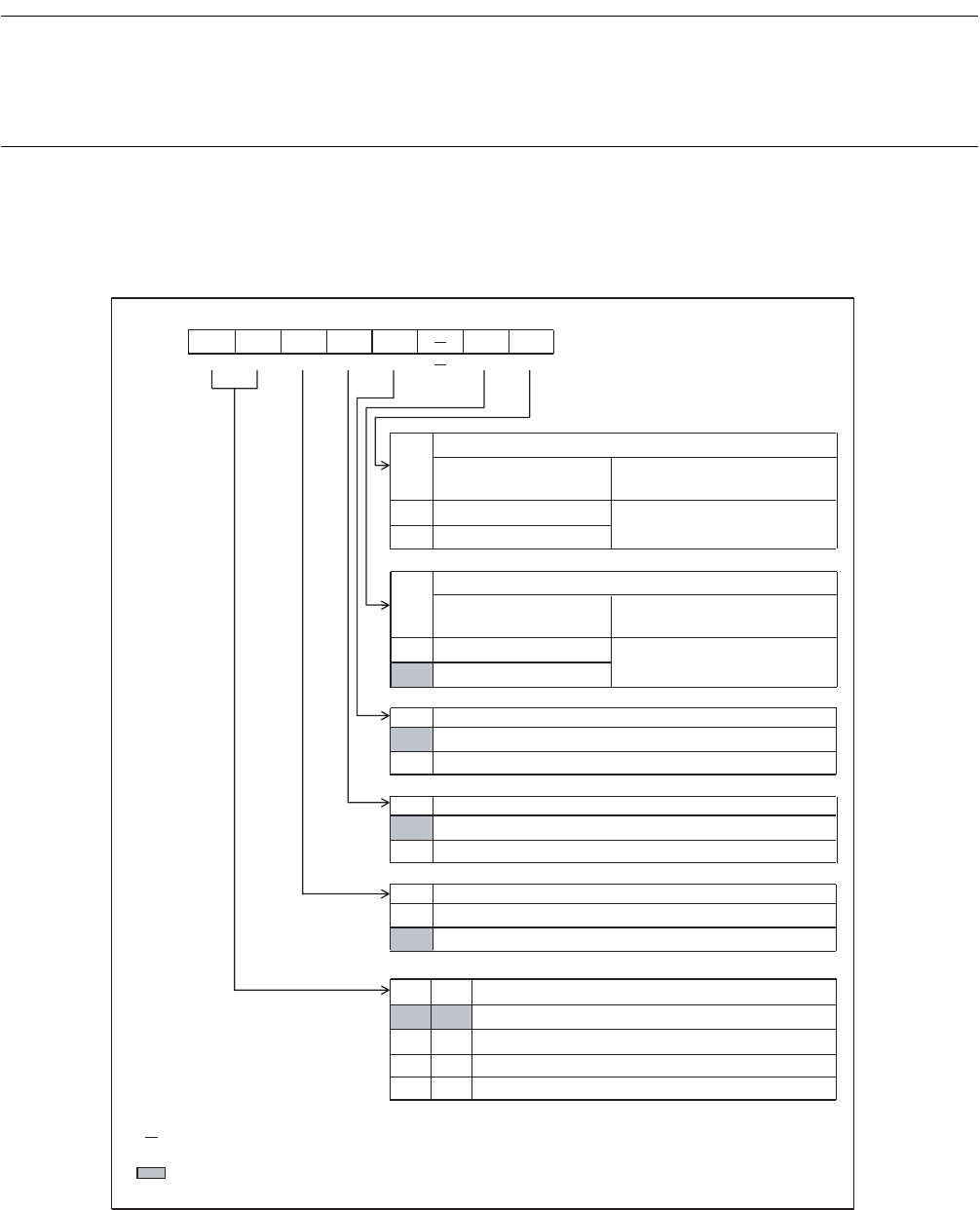
Figure 13.4-4 Serial Status and Data Register (SSD)
RD8/
RP
0
1
TD8/
TP
0
1
RIE
0
1
TIE
0
1
TDRE
0
1
RDRFORFE
00
01
10
11
bit7 bit6 bit5 bit4 bit3bit2 bit1 bit0
002A
H
RDRF ORFE TDRE
TIE RIE
TD8/TP
RD8/RP
00100-1X
B
R R R/W R/W R/W R/W R
R/W
R
X
Address
Initial value
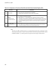
Bit-8 receiving data/parity bit
Parity used
Parity not used
(SMC: PEN = 1)
(SMC: PEN = 0)
Detects odd parity.
Detects even parity.
Bit-8 receiving data*
Bit-8 transmitting data/parity bit
Parity used
(SMC: PEN = 1)
Parity not used
(SMC: PEN = 0)
Adds odd parity.
Adds even parity.
Sets bit-8
transmitting data.*
Reception interrupt request enable bit
Disables output of reception interrupt requests.
Enables output of reception interrupt requests.
Transmission interrupt request enable bit
Disables output of transmission interrupt requests.
Enables outp
ut of transmission interrupt requests.
Transmitted data flag bit
Data to be transmitted included
Data to be transmitted not included
Received data flag bit/Overrun/Framing error flag bit
No data
Framing error
Normal data
Overrun error (previous data remaining)
: Readable/Writ
able
: Read only
: Unused
: Undefined
: Initial value
: Effective only when data length is 9 bits (SMC: MC1 and MC0 = 10
B
and 11
B
, operating mode is 2 or 3.)
*