


47
CHAPTER 3 CPU
3.5.2 External Reset Pin
The external reset pin generates a reset by "L" level input. When an option setting for
enabling reset output is selected, the "L" level signal is output depending on the
internal reset source.
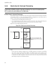
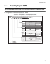
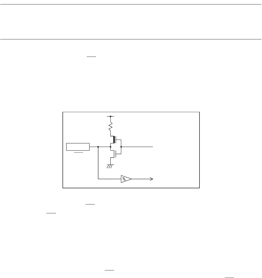
■ Block Diagram of External Reset Pin
The external reset pin (RST) on models with supported reset output has hysteresis input and pull-up N-ch
open drain output.
The external reset pin on models without supported reset output is used only as the pin dedicated to reset
input.
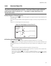
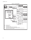
Figure 3.5-2 is a block diagram of the external reset pin.
Figure 3.5-2 Block Diagram of External Reset Pin
■
Function of the External Reset Pin
The external reset pin (RST) generates an internal reset signal by making use of "L" level input.
The RST
outputs the "L" level signal according to the internal reset source and oscillation stabilization wait
time applied following a reset. The internal reset source may be software reset, watchdog reset, or power-
on reset.
Note:
External reset input is accepted asynchronously regardless of the internal clock.
Initialization of the internal circuits requires a clock. In particular, for operations with an external clock,
the clock must be input when a reset signal is input.
Internal pull-up control for RST
is not available for MB89F202/F202RA. To ensure proper external
reset control in MB89F202/F202RA, an external pull-up (recommend 100 kΩ) for RST
pin must be
required.
P-ch
N-ch
RST
Pull-up resistor
Approx. 50kΩ for 5 V
(Not available for
MB89F202)
Pin Internal reset source
Internal reset signal