


227
CHAPTER 10 EXTERNAL INTERRUPT CIRCUIT 1 (EDGE)
10.2 Configuration of External Interrupt Circuit 1
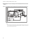
External interrupt circuit 1 comprises the following two blocks:
• Edge detecting circuits (0 to 2)
• External interrupt control 1 registers 1, 2 (EIC1, EIC2)
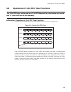
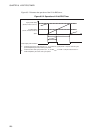
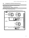
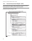
■ Block Diagram of External Interrupt Circuit 1
Figure 10.2-1 Block Diagram of External Interrupt Circuit 1 (EIC1, EIC2)
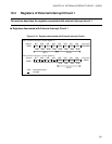
EIR1 SL11 SL10 EIE1 EIR0 SL01 SL00 EIE0
EIR2 SL21 SL20 EIE2
P34/TO/INT10
P35/INT11
10
01
11
10
01
11
P36/INT12
10
01
11
Pin
Edge detecting circuit 1
Pin
Selector
Edge detecting circuit 0
Selector
External interrupt 1
control register 1
(EIC1)
Interrupt request
(IRQ0)
Interrupt request
(IRQ1)
Internal data bus
Edge detecting circuit 2
Pin
Selector
External interrupt 1
control register 2
(EIC2)
Interrupt request (IRQ2)