


269
CHAPTER 12 A/D CONVERTER
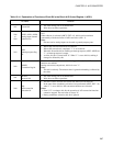
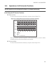
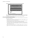
Table 12.4-2 Explanation of Functions of Each Bit in A/D Control Register 2 (ADC2)
Bit name Function
bit7 Unused bit
• The value during read is not determined.
• Write does not affect operations.
bit6,
bit5
RESV4,RESV3:
Reserved bits
• This bit is a reserved bit.
• Be sure to write 00
B
to these bits.
bit4 ADCK:
Selecting an input
clock bit
This bit is used to select an input clock for activation of A/D conversion
functions in the state where continuous activation is performed (EXT = 1).
When this bit is "0", the internal clock with an oscillation frequency (selected
using the output of a time-base timer) divided by 2
8
is selected. When "1", the
output of an 8/16-bit capture timer/counter (TO: 16-bit mode) is selected.
bit3
ADIE:
Enabling an interrupt
request bit
This bit is used to enable and disable the output of an interrupt to the CPU.
When this bit and the interrupt request flag bit (ADC1: ADI) are "1", an
interrupt request is output.
bit2
RESV2:
Reserved bit
• This bit is a reserved bit.
• Be sure to write "0" to this bit.
bit1
EXT:
Bit for enabling
continuous activation
This bit is used to select whether the A/D conversion functions are to be
activated with software or activated continuously in synchronization with an
input clock.
When this bit is "0", software activation with the bit for activating A/D
conversion (ADC1: AD) is enabled. When "1", continuous activation on the
rising edge of the clock selected using the bit for selecting an input clock
(ADC2: ADCK) is enabled.
bit0
RESV1:
Reserved bit
• This bit is a reserved bit.
• Be sure to write "1" to this bit.