


68
CHAPTER 3 CPU
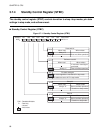
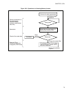
3.7.5 Diagram for State Transition in Standby Mode
Figure 3.7-2 shows the state transition diagram in standby mode.
■ Diagram for State Transition in Standby Mode
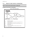
Figure 3.7-2 State Transition Diagram
Power turned on
Power-on reset
Oscillation
stabilization wait
reset mode
Reset mode
RUN mode Sleep mode
Oscillation
stabilization wait
Stop mode
(9)
(4)
(1) (2)
(3)
(6)
(5)
(11)
(8)
(7)
(10)
(1)
: Cancellation of reset input
(2)
(3)
(4)
(5)
(6)
(7)
(8) (9)
(10) (11)
: Reset sources (multiple)
: Transition to sleep mode by the sta
ndby control register (STBC: SLP = 1)
: External reset input
: Transition to stop mode by the standby control register (STBC: STP = 1)
: External interrupt request
: External reset input
: Interrupt request
: Time-base timer overflow (end of oscillation stabilization wait time)