


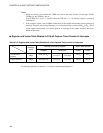
188
CHAPTER 8 8/16-BIT CAPTURE TIMER/COUNTER
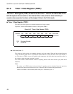
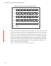
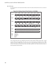
● 16-bit mode
To operate timer 0 as the interval timer function in the 16-bit mode, the function must be set as shown in
Figure 8.6-4 .
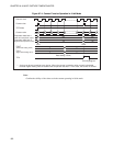
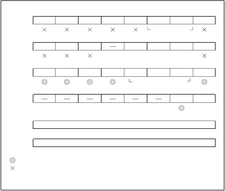
Figure 8.6-4 Setting of Interval Timer Function in 16-bit Mode
In the 16-bit mode, timers are controlled by the timer 0 control register (TCR0), but the timer 1 control
register (TCR1) must be initialized. The values to be set in the data register are the higher 8 bits of TDR1
and the lower 8 bits of TDR0 (16 bits in total). The values are compared with the 16-bit counter value. The
16 bits of the counter are cleared at the same time. Other operations in the 16-bit mode are the same as
timer 0 operation in the 8-bit mode.
bit7 bit6 bit5 bit4 bit3 bit2 bit1 bit0
TCCR CPIF
CFCLR
CPIEN
CCMSK
TCMSK EDGS1 EDGS0
RESV
TCR1 TIF1 TFCR1 T1IEN TCS12 TCS11 TCS10
TSTR1
TCR0 TIF0
TFCR0 T0IEN
CINV TCS02
TCS01
TCS00 TSTR0
TCR2
PEN TSEL
0
TDR1
TDR0
: Used bit
: Unused bit
: Set "0"
Setting of 00
Setting of a value
other than 111
Setting of higher 8 bits of interval time
Setting of lower 8 bits of interval time
1
1
1
0
: Set "1"
1