


341
CHAPTER 15 BUZZER OUTPUT
15.2 Configuration of the Buzzer Output
The buzzer output consists of the following two blocks:
• Buzzer output selector
• Buzzer register (BZCR)
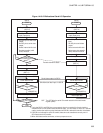
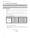
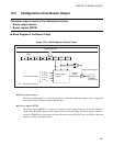
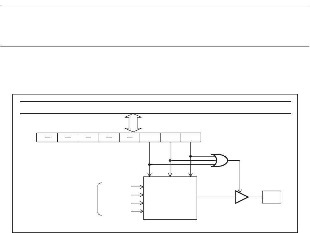
■ Block Diagram of the Buzzer Output
Figure 15.2-1 Block Diagram of Buzzer Output
● Buzzer output selector
The buzzer output selector is a circuit for selecting one of the four frequencies (square waves) output from
the time-base timer. The buzzer register (BZCR) sets it.
● Buzzer register (BZCR)
The buzzer register (BZCR) is a register for setting the buzzer output frequency and enable the buzzer
output. When the BZCR register sets an output frequency (other than 000
B
), the buzzer output is enabled so
that the P37/BZ/PPG pin automatically becomes the buzzer output (BZ) pin. Even if the PPG pin has been
enabled, the BZ pin has higher priority.
F
CH
BZ2 BZ1 BZ0
BZCR
P37/BZ/PPG
2
13
/F
CH
2
12
/F
CH
2
11
/F
CH
2
10
/F
CH
Internal data bus
From time-base timer
Buzzer output
selector
Selector
output
Buzzer enable signal
Pin
: Oscillation frequency