187
CHAPTER 8 8/16-BIT CAPTURE TIMER/COUNTER
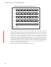
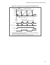
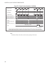
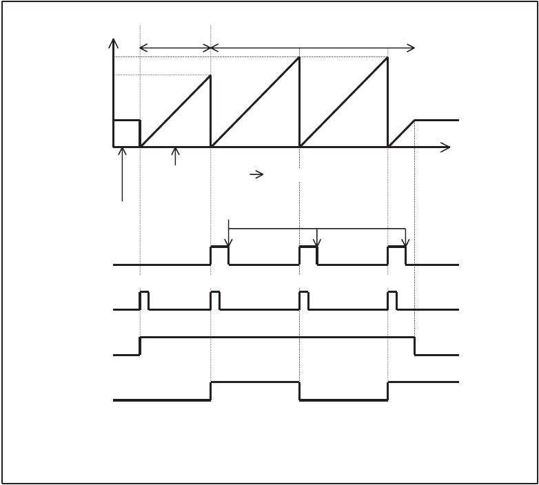
Figure 8.6-3 Interval Timer Function Operation in 8-bit Mode (Timer 0)
*2:
Counter value
Comparison
value
(E0
H
)
Comparison value (FF
H
)
FF
H
E0
H
80
H
00
H
TDR0 value
TDR0
value
(E0
H
)
(E0
H
FF
H
(*1)
Time
Clear by program
TIF0 bit
Counter clear
(*2)
Start Match
Match
Match
TSTR0 bit
TO pin
*1:
If the data register is rewritten when the counter is in operation, the interval timer
function becomes valid from the next cycle.
When timer 0 is started or when a match is detected, the counter is cleared and the
values in the data register are loaded to the comparator data latch.
)


