


168
CHAPTER 8 8/16-BIT CAPTURE TIMER/COUNTER
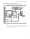
8.3 Pins of 8/16-bit Capture Timer/Counter
This section provides pins of 8/16-bit capture timer/counter and a block diagram for
these pins.
■ Pins of 8/16-bit Capture Timer/Counter
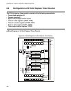
8/16-bit capture timer/counter pins include P33/EC and P34/TO/INT10.
● P33/EC pin
The P33/EC pin shares functions of the general-purpose I/O port (P33) and the external clock for the timer
or capture input pin (EC).
EC:
When external clock input is selected (TCR0: TCS02, TCS01, TCS00=111
B
) in timer 0 for the 8-bit
mode or in the 16-bit mode, the clocks input to this pin are counted. In the capture function, this pin is
also used as an input pin. When using this pin as the EC pin, set 0 in the port data 3-direction register
(DDR3: bit3) and set the output transistor to OFF to enable the EC pin to be used as an input port.
● P34/TO/INT10 pin
The P34/TO/INT10 pin shares functions of the general-purpose I/O port (P34) and the square wave output
pin for the timer (TO). It also shares a function of the input pin for external interrupt 1 (INT10).
TO:
In timer 0 or 1 (switching allowed) for the 8-bit mode or in the 16-bit mode, a square wave is output
from this pin. If square wave output is enabled (TCR2: PEN = 1), the P34/TO/INT10 pin automatically
functions as an output pin without reference to the port 3-direction register (DDR3: bit4); it functions as
the TO pin. The TCR2: TSEL is used to select whether timer 0 output or timer 1 output is to be used.