


150
CHAPTER 7 8-BIT PWM TIMER
7.7 Operations of the 8-bit PWM Timer Functions
This section describes the operations of the 8-bit PWM timer functions.
■ Operations of the 8-bit PWM Timer Functions
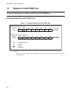
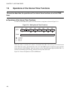
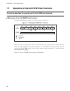
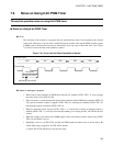
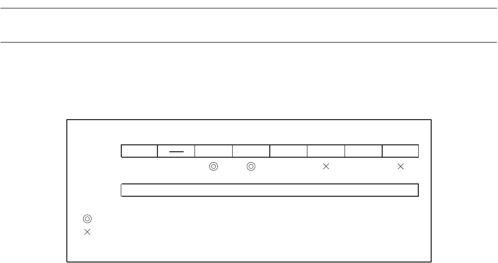
To enable 8-bit PWM timer functions, set registers as shown in Figure 7.7-1 .
Figure 7.7-1 Setting 8-bit PWM Timer Functions
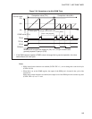
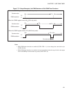
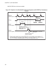
When the counter is activated, the counter is incremented from 00
H
at the start-up of the selected count
clock. The output (PWM waveform) of the PWM pin is "H" until a match between the counter value and
the value set in the COMR register is found. Once a match is found, the output is "L" until the counter
value overflows (FF
H
→ 00
H
).
Figure 7.7-2 shows the PWM waveform output to the PWM pin.
bit7 bit6 bit5 bit4 bit3 bit2 bit1 bit0
CNTR
P/TX P1 P0 TPE TIR OE TIE
1 11
COMR
1
1
Set an H-level pulse width (compare value).
: Used bit
: Unused bit
: Set "1".