


149
CHAPTER 7 8-BIT PWM TIMER
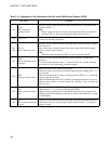
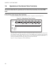
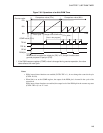
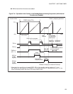
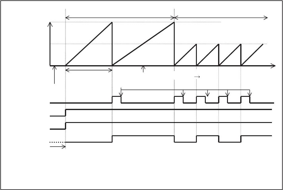
Figure 7.6-2 Operations of an 8-bit PWM Timer
Notes:
• While interval timer functions are enabled (CNTR: TPE = 1), do not change the count clock cycle
(CNTR: P1, P0).
• When 00
H
is set to the COMR register, the output of the PWM pin is inverted in the cycle of the
count clock.
While interval timer functions are enabled, the output level of the PWM pin in the counter stop state
(CNTR: TPE = 0) is at "L" level.
FF
H
(FF
H
)
(80
H
)(FF
H
)
80
H
00
H
(FF
H
80
H
)
*
Counter value
Comparison value
Timer cycle
Change of the COMR value
Time
COMR value
Clear in the program
TIR bit
TPE bit
OE bit
PWM pin
When the bit to control the output pin (OE) is "0", the pin functions as a
general-purpose I/O port pin (P50).
If the PWM compare register (COMR) value is changed during counter operation, the value
takes effect at the next cycle.
*:
Comparison value