


54
CHAPTER 3 CPU
3.6.2 Clock Controller
The clock controller consists of the following six blocks:
• Oscillation circuit
• System clock selector
• Clock controller
• Oscillation stabilization wait time selector
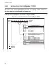
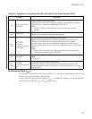
• System clock control register (SYCC)
• Standby control register (STBC)
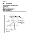
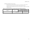
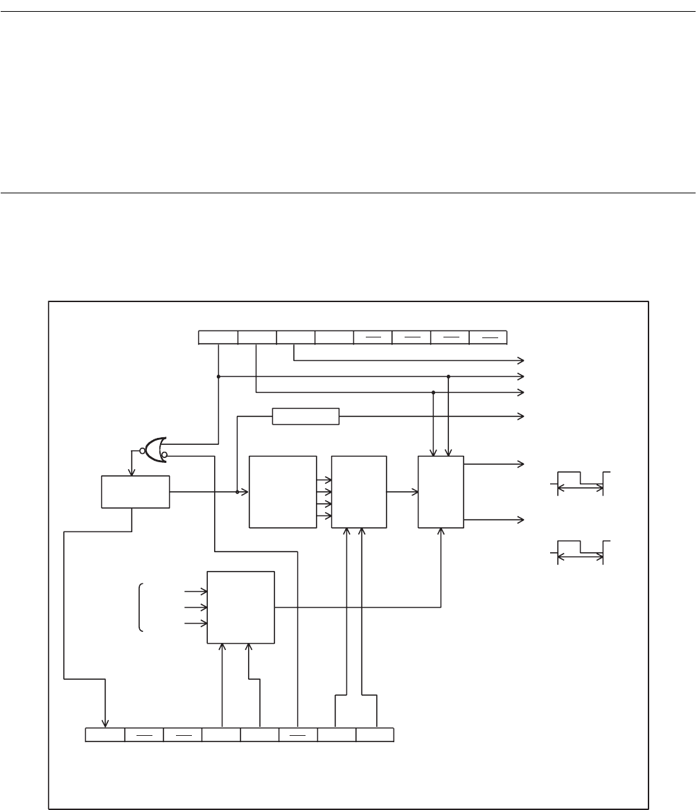
■ Block Diagram of Clock Controller
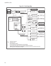
Figure 3.6-4 is a block diagram of the clock controller.
Figure 3.6-4 Block Diagram of Clock Controller
STP
SLP SPL RST
SCM
WT1
WT0 CS1CS0
2
14
/F
CH
2
17
/F
CH
2
18
/F
CH
1t
INST
1t
INST
F
CH
t
INST
Standby control register (STBC)
Pin control
Stop
Sleep
Clock for time-base
timer
1/2 frequency
Clock
generator
System clock selector
Pre-scaler
1/4 frequency
1/8 frequency
1/16 frequency
1/64 frequency
Selector
Clock
control
circuit
Supplied to the CPU
Supplied to peripheral
circuits
From the
time-base
timer
Oscillation
stabilization
wait time
selector
System clock control register (SYCC)
: Oscillation frequency
: Instruction cycle