361
CHAPTER 17 FLASH MEMORY
17.3 Starting the Flash Memory Automatic Algorithm
Four types of commands are available for starting the flash memory automatic
algorithm: Read/Reset, Write, and Chip Erase.
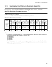
■ Command Sequence Table
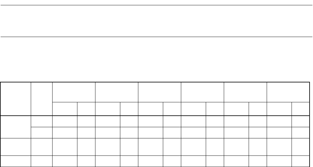
Table 17.3-1 lists the commands used for flash memory write/erase.
Table 17.3-1 Command Sequence Table
Command
sequence
Bus
write
access
1st bus write
cycle
2nd bus write
cycle
3rd bus write
cycle
4th bus read/
write cycle
5th bus write
cycle
6th bus write
cycle
Address Data Address Data Address Data Address Data Address Data Address Data
Read/Reset
(*)
1 XXXX F0 ----------
4FAAAAAF55455FAAAF0RARD----
Write
program
4FAAAAAF55455FAAAA0PAPD----
Chip Erase 6 FAAA AA F554 55 FAAA 80 FAAA AA F554 55 FAAA 10
*: Both of the two types of Read/Reset commands can reset the flash memory to read mode.
Notes:
• The addresses shown in the table are those on the CPU memory map. All addresses and data are represented in
hexadecimal notation. The letter X indicates an appropriate value.
RA: Read address
PA: Write address.
RD: Read data
PD: Write data.
• The flash memory can only accept the command sequences mentioned on the above table (Read/Reset, Write
program, Chip Erase), other command sequences are strictly prohibited to be sent to the flash memory or else the
flash memory may become malfunction.


