


155
CHAPTER 7 8-BIT PWM TIMER
7.9 Notes on Using 8-bit PWM Timer
This section provides notes on using 8-bit PWM timer.
■ Notes on Using 8-bit PWM Timer
● Error
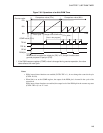
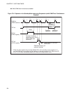
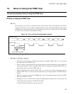
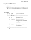
The activation of the counter by a program does not synchronize the start of an increment by the selected
count clock. Therefore, as an error until a match between the counter value and the PWM compare register
(COMR) value is detected, the time may be shortened by up to one cycle of the count clock cycle. Figure
7.9-1 shows an error until the count operation is started.
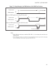
Figure 7.9-1 Error until the Count Operation is Started
● Notes on setting by a program
• While interval timer functions or PWM timer functions are enabled (CNTR: TPE = 1), do not change
the count clock cycle (CNTR: P1, P0).
• If the user wants to switch between the interval timer function and the PWM timer function (CNTR: P/
TX), proceed when the counter is stopped (CNTR: TPE = 0), interrupts are disabled (CNTR: TIE = 0),
and interrupt requests are cleared (CNTR: TIR = 0).
• When the interrupt request flag bit (CNTR: TIR) is "1" and the bit to enable an interrupt request is
enabled (CNTR: TIE = 1), recovery from interrupt handling is no longer possible. The TIR bit must be
cleared.
• When the counter value matches the COMR register value concurrently with the counter stop (CNTR:
TPE = 0), the TIR bit is not set.
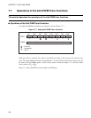
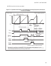
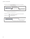
• Depending on how to set TPE, P/TX, and OE, the PWM output waveform varies as shown below. Be
careful when using a program to set TPE, P/TX, and OE.
(1) When TPE, P/TX, and OE are set at the same time:
00
H
Counter value
Count clock
One cycle
Error Cycle of 00
H
Activating the counter
01
H 02
H
03
H
04
H