


292
CHAPTER 13 UART
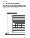
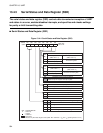
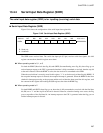
13.4.2 Serial Rate Control Register (SRC)
The serial rate control register (SRC) controls the data transfer rate (baud rate) in
asynchronous transfer mode. The SRC selects the input clock and sets the transfer rate
for the dedicated baud rate generator.
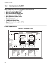
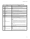
■ Serial Rate Control Register (SRC)
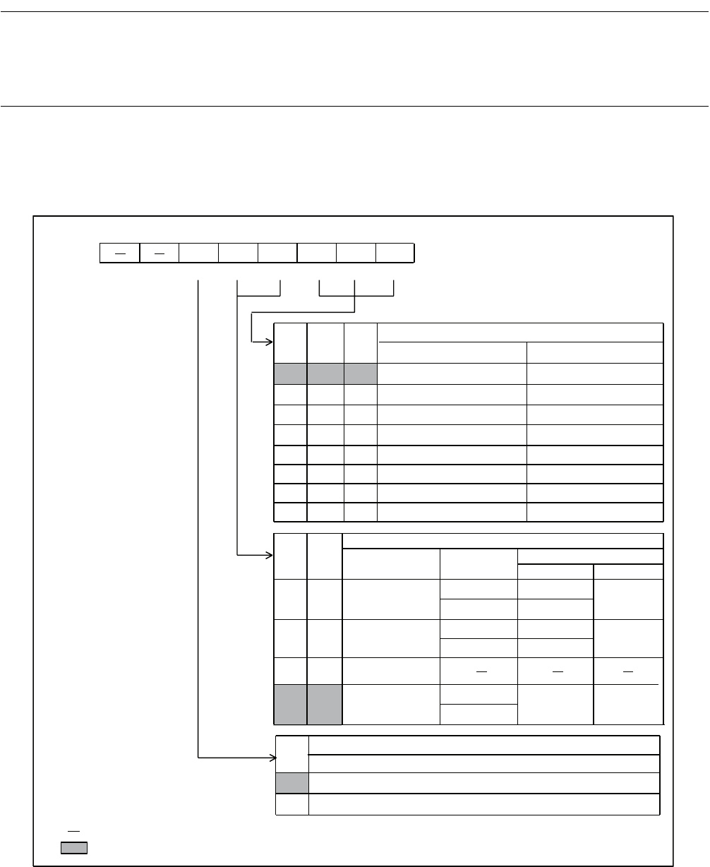
Figure 13.4-3 Serial Rate Control Register (SRC)
RC2 RC1 RC0
000 83/12019 0.8/1.25M
001
166/6010
1.6/625k
010
333/3005
3.2/313k
011
666/1503
6.4/156k
100
1331/751
12.8/78k
1 0 1 2662/375 25.6/39k
110
13/78125
1.6/625k
1 1 1 102/9766 12.8/78k
CS1
CS0
016
00
164
1
016
01
164
2
10
0
11
1
8 1
CR
0
1
bit7 bit6 bit5 bit4 bit3bit2 bit1 bit0
0029
H
CR
CS1
CS0
RC2
RC1 RC0
--011000
B
R/W R/W R/W R/W R/W R/W
R/W
Address
Initial value
Baud rate selection bits
Asynchronous
(
µ
s/baud)
Synchronous (
µ
s/baud)
Clock input selection bits
Clock input
CR bit
Clock frequency divider
Asynchronous
Synchronous
External clock
PWM timer output
Unused
Dedicated baud
rate generator
Clock rate input selection bit
Effective only in asynchronous transfer mode (SMC: SMDE = 1)*
1/16 of the clock input
1/64 of the clock input
However, when the dedicated baud rate generator is used (CS1 and CS0 = 11
B
),
it is fixed at 1/8.
* :
: Readable/Writable
: Initial value
: Unused