


29
CHAPTER 3 CPU
3.2.1 Condition Code Register (CCR)
The condition code register (CCR) is the lower 8 bits of the program status register
(PS). The condition code register consists of bits (C, V, Z, N, and H) for indicating the
results of arithmetic operations or data to be transferred and control bits (I, IL1, and IL0)
for controlling the acceptance of interrupt requests.
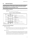
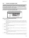
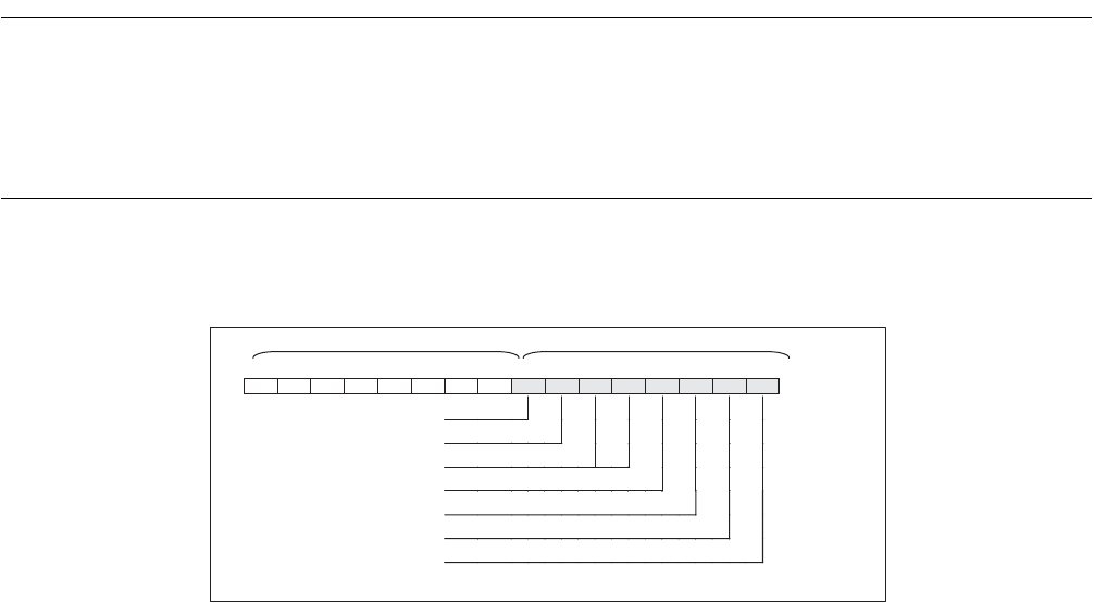
■ Configuration of the Condition Code Register (CCR)
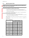
Figure 3.2-2 Configuration of Condition Code Register
■
Bits for Indicating Arithmetic Operation Results
● Half carry flag (H)
When a carry from bit3 to bit4 or a borrow from bit4 to bit3 occurs as a result of an arithmetic operation,
the half carry flag is set to "1". Otherwise, the half carry flag is cleared with "0". The half carry flag is
intended only for decimal adjustment instructions, and thus should not be used for operations other than
addition or subtraction.
● Negative flag (N)
When the highest bit becomes "1" as a result of an arithmetic operation, the negative flag is set to "1".
When it becomes "0", it is cleared with "0".
● Zero flag (Z)
When the result of an arithmetic operation is "0", the zero flag is set to "1". Otherwise, the zero flag is
cleared with "0".
● Overflow flag (V)
When a complement on 2 overflow occurs as a result of an arithmetic operation, the overflow flag is set to
"1". Otherwise, the overflow flag is cleared with "0".
● Carry flag (C)
When a carry from bit7 or a borrow to bit7 occurs as a result of an arithmetic operation, the carry flag is set
to "1". Otherwise, the carry flag is cleared with "0". The shift instruction causes the value to be shifted out.
RP CCR
bit15 bit14bit13 bit12bit11bit10 bit9 bit8 bit7 bit6 bit5 bit4 bit3 bit2 bit1 bit0 CCR initial value
PS R4 R3 R2 R1 R0
- - -
H I IL1 IL0 N Z V C
X011XXXX
B
Half carry flag
Interrupt enable flag
Interrupt level bits
Negative flag
Zero flag
Overflow flag
Carry flag
X: Undefined