


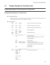

129
CHAPTER 6 WATCHDOG TIMER
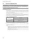
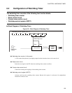
6.2 Configuration of Watchdog Timer
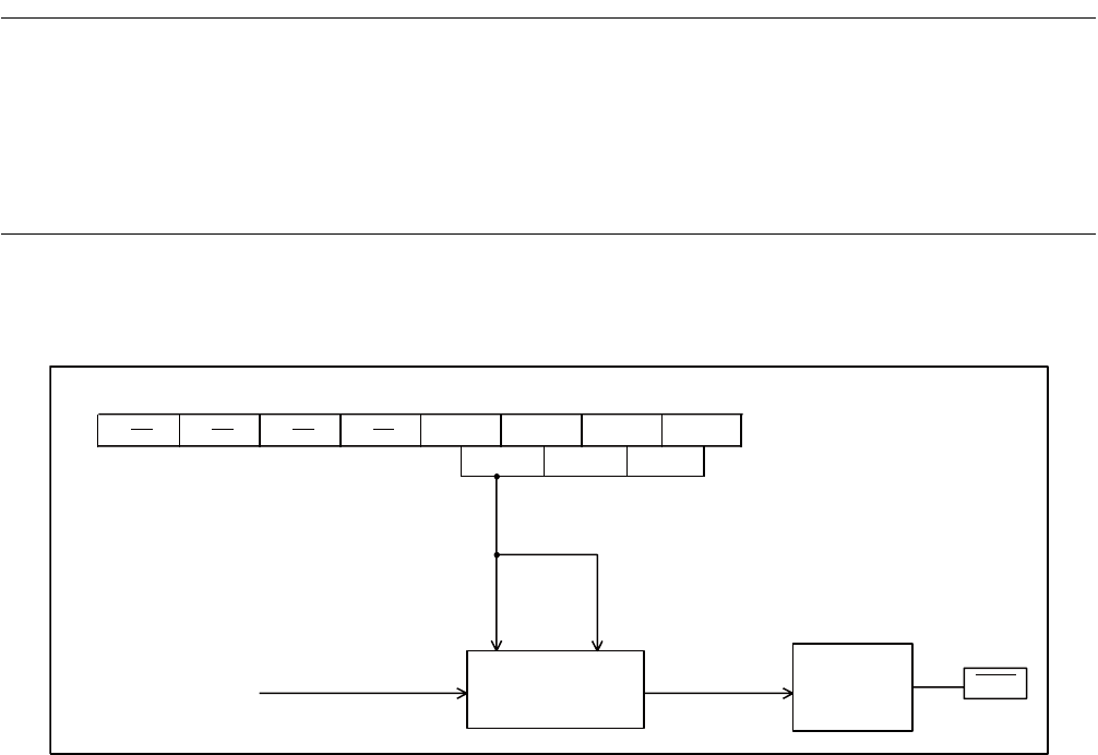
The watchdog timer consists of the following four function blocks.
• Watchdog timer counter
• Reset control circuit
• Counter clear control circuit
• Watchdog control register (WDTC)
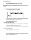
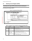
■ Block Diagram of Watchdog Timer
Figure 6.2-1 Block Diagram of Watchdog Timer
● Watchdog timer counter (1-bit counter)
A 1-bit counter that operates by accepting output from the time-base timer as the count clock.
● Reset control circuit
Sends the reset signal to the CPU when the watchdog timer counter overflows.
● Counter clear control circuit
Controls the clearing and stopping of the watchdog timer counter.
● Watchdog control register (WDTC)
Activates and clears the watchdog timer counter. Because this register is write-only, bit manipulation
instructions cannot be used.
WTE3 WTE2
WTE1 WTE0
RST
Watchdog control register (WDTC)
Watchdog timer
Clear Start
(Time-
base timer
output)
1-bit counter
Overflow
Reset
control
circuit
2
22
/F
CH