


328
CHAPTER 14 8-BIT SERIAL I/O
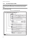
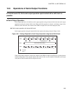
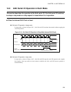
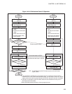
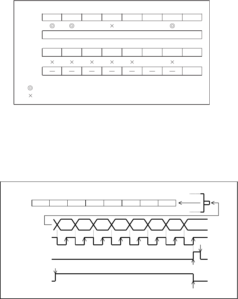
● Serial input operation using external shift clock
Serial input operation with the external shift clock requires the settings shown in Figure 14.7-2 .
Figure 14.7-2 Settings Required for Serial Input Operation using External Shift Clock
When serial input operation is allowed, the value of the SI pin is captured and held in the SDR in
synchronization with the rising edge of the external shift clock. When serial input is completed,
immediately read the SDR and allow serial input operation (SMR: SST = 1) to prepare for the input of the
next data. In this case, when the 8-bit serial I/O is idle (state in which it is waiting for the output of the next
data), keep the external shift clock at a "H" level.
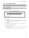
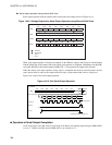
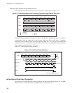
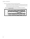
Figure 14.7-3 shows 8-bit serial input operation.
Figure 14.7-3 8-bit Serial Input Operation
■
Operation at Serial Input Completion
At the rising edge of the shift clock for the serial data of the 8th bit, the interrupt request flag bit (SMR:
SIOF) is set to "1" and the serial I/O start bit (SMR: SST) is set (cleared) to "0".
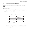
bit7 bit6 bit5 bit4 bit3 bit2 bit1 bit0
SMR SIOF SIOE SCKE SOE CKS1 CKS0 BDS SST
0 11 1
SDR
DDR3
0 0
SSEL
SSEL
1
0
1
Reception data storage
: Used bit
: Unused bit
: Set "0"
: Set "1"
bit7 bit6 bit5 bit4 bit3 bit2 bit1 bit0
SDR #7 #6 #5 #4 #3 #2 #1 #0
#7 #6 #5 #3#4 #2 #1 #0
07654321
For MSB first
SI pin
Serial input data
Shift clock
Clear via program
SIOF bit
Transfer start
SST bit
Interrupt request
Automatic clear at transfer end