8
CHAPTER 1 OVERVIEW
1.5 Pin Assignment
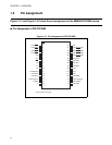
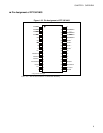
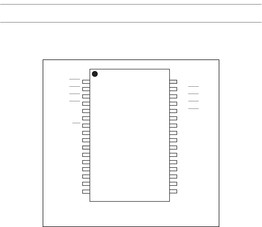
Figure 1.5-1 and Figure 1.5-2 show the pin assignment of the MB89202/F202RA series.
■ Pin Assignment of DIP-32P-M06
Figure 1.5-1 Pin Assignment of DIP-32P-M06
1
2
3
4
5
6
7
8
9
10
11
12
13
14
15
16
V
CC
P03/INT23/AN7
P02/INT22/AN6
P01/INT21/AN5
P00/INT20/AN4
P43/AN3*
P42/AN2*
P41/AN1*
P40/AN0*
P72*
P71*
P70*
P50/PWM
P30/UCK/SCK
P31/UO/SO
P32/UI/SI
32
31
30
29
28
27
26
25
24
23
22
21
20
19
18
17
P04/INT24
P05/INT25
P06/INT26
P07/INT27
P60
P61
RST
X0
X1
V
SS
P37/BZ/PPG
P36/INT12
P35/INT11
P34/TO/INT10
P33/EC
C
* : Large-current drive type


