


146
CHAPTER 7 8-BIT PWM TIMER
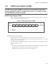
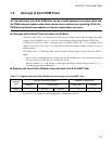
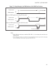
● While the PWM timer is operating:
Specify the "H" level width of a pulse in the register to which the value that is compared with the counter
value is to be set.
Until the settings written to this register match the counter value, "H" is output from the PWM pin. When a
match is found, "L" is output until the counter value overflows.
If a value is written to the COMR register while the counter is operating, the value takes effect at the next
cycle (after overflow).
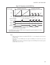
Note:
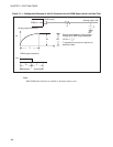
The settings and cycle of the COMR register, while the PWM timer is operating, can be calculated
using the following formula. The gear function, however, affects the instruction cycle.
COMR register value = duty ratio (%) × 256
PWM wave cycle = count clock cycle × instruction cycle × 256