


78
CHAPTER 4 I/O PORTS
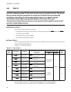
4.2 Port 0
Port 0 is a general-purpose I/O port and may also serve as peripheral inputs. The pins of
this port can be used for peripherals or normal port function that can be selected
according to the setting of a bit corresponding to the pin on a specific register.
This section mainly explains the general-purpose I/O function of the port.
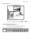
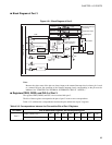
This section also describes the structure, pins, and associated registers of port 0 and
provides a block diagram of pins.
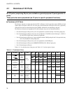
■ Structure of Port 0
Port 0 comprises the following four elements:
• General-purpose I/O pins, external interrupt 2, and analog input pins (P00/INT20
/AN4 to P07/INT27)
• Port 0 data register (PDR0)
• Port 0 data direction register (DDR0)
• Port 0 pull-up setting register (PUL0)
■
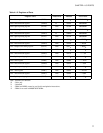
Pins of Port 0
Port 0 has eight general-purpose I/O pins. When used as input pins at the same time, these pins can be also
used as external interrupt input pins.
Table 4.2-1 lists the pins of port 0.
For circuit type, see Section "1.7 Pin Functions Description " and "1.8 I/O Circuit Types ".
For pin operation when used as analog input, see "CHAPTER 12 A/D CONVERTER ".
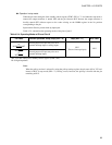
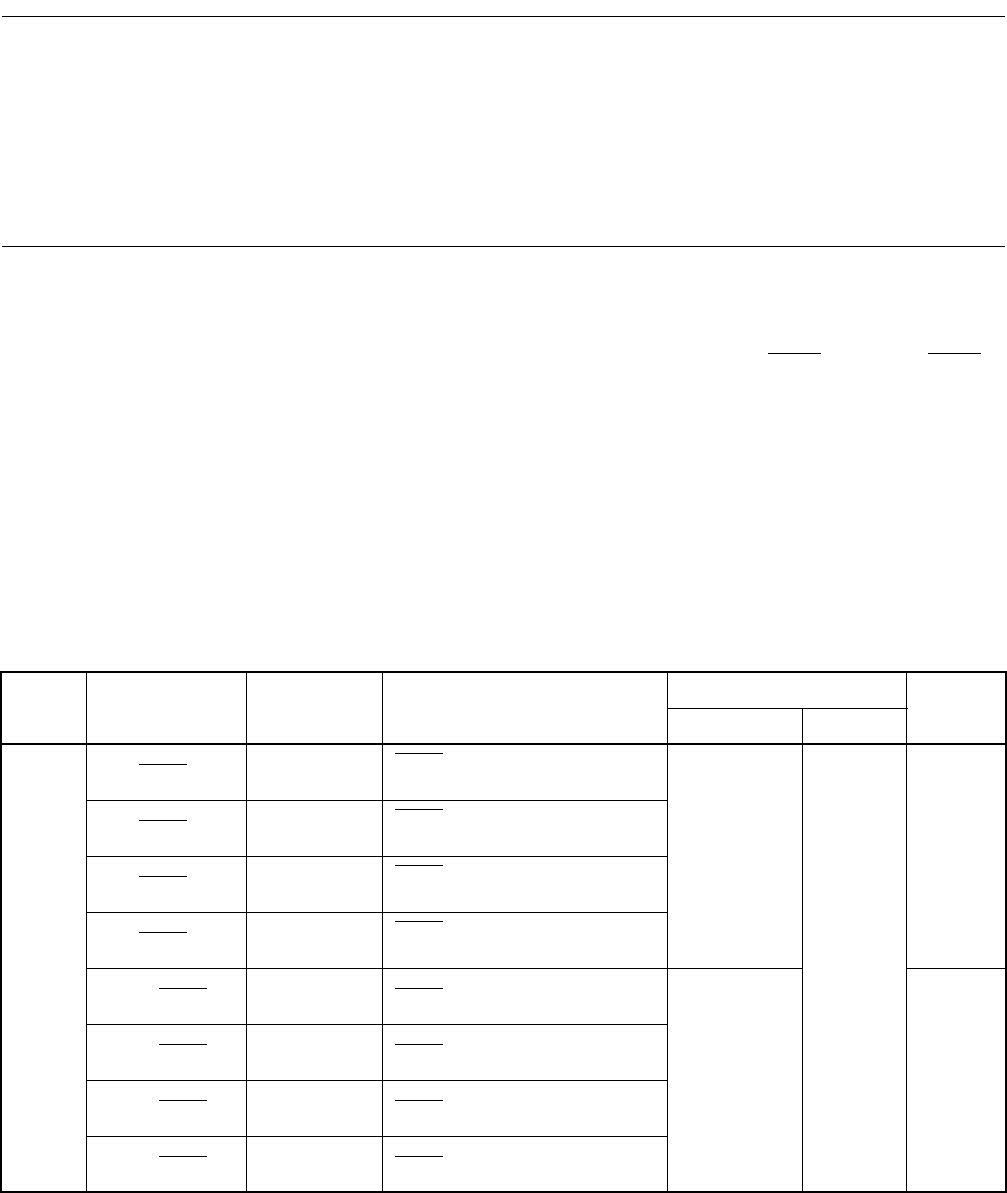
Table 4.2-1 Pins of Port 0
Port
name
Pin name Function
Peripherals for which a pin
may serve
Input and output form
Circuit
type
Input Output
Port 0
P00/INT20
/AN4
P00 general-
purpose I/O
INT20
: external interrupt input 20
AN4 : analog input 4
Analog CMOS
hysteresis
CMOS
G
P01/INT21
/AN5
P01 general-
purpose I/O
INT21
: external interrupt input 21
AN5 : analog input 5
P02/INT22
/AN6
P02 general-
purpose I/O
INT22
: external interrupt input 22
AN6 : analog input 6
P03/INT23/AN7
P03 general-
purpose I/O
INT23
: external interrupt input 23
AN7 : analog input 7
P04/INT24
P04 general-
purpose I/O
INT24
: external interrupt input 24
CMOS
hysteresis
D
P05/INT25
P05 general-
purpose I/O
INT25
: external interrupt input 25
P06/INT26
P06 general-
purpose I/O
INT26
: external interrupt input 26
P07/INT27
P07 general-
purpose I/O
INT27
: external interrupt input 27