


200
CHAPTER 8 8/16-BIT CAPTURE TIMER/COUNTER
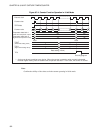
8.11 Program Example for 8/16-bit Capture Timer/Counter
This section provides program examples of the 8/16-bit capture timer/counter.
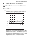
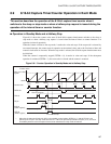
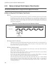
■ Program Example of Interval Timer Function
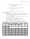
● Processing specifications
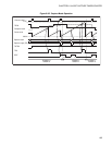
• In the 8-bit mode, only timer 0 is used to generate a 20 ms interval timer interrupt.
• When the interval time has elapsed, the square wave to be inverted is output to the TO pin.
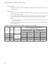
• At 12.5-MHz oscillation (F
CH
), the TDR0 value whose interval time becomes 20 ms at the maximum
gear speed (1 instruction cycle = 4/F
CH
) is shown below. The count clock is 256t
INST
of the internal
count clock.
TDR0 value = 20 ms/(256 × 4/12.5 MHz) - 1 = 244 (F4
H
)
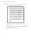
● Coding example
TCCR EQU 0019H ; Address of capture control register
TCR1 EQU 001AH ; Address of timer 1 control register
TCR0 EQU 001BH ; Address of timer 0 control register
TCR2 EQU 0020H ; Address of timer output control register
TDR1 EQU 001CH ; Address of timer 1 data register
TDR0 EQU 001DH ; Address of timer 0 data register
TIF0 EQU TCR0:7 ; Defines the timer 0 interrupt request flag bit.
ILR1 EQU 007BH ; Address of interrupt request setting register
INT_V DSEG ABS ; [DATA SEGMENT]
ORG 0FFF0H
IRQD DW WARI ; Sets an interrupt vector.
ENDS
;------------------------Main program---------------------------------------------------------------------------------
CSEG ; [CODE SEGMENT]
; The stack pointer (SP), etc., is already initialized.
:
CLRI ; Disables the interrupt.
MOV ILR1,#10111111B ; Sets the interrupt level to 2.
MOV TCR0,#01001010B ; Clears the timer 0 interrupt request flag, increments the
counter at a rising edge, selects 256t
INST
, and stops the
operation.
MOV TCR1,#01000010B ; Clears the timer 1 interrupt request flag, prohibits
interrupt request output, sets a mode other than the 16-
bit mode, and stops the operation.
MOV TDR0,#F4H ; Sets the value (interval time) to be compared with the
counter value.