


293
CHAPTER 13 UART
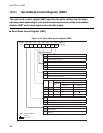
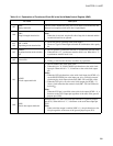
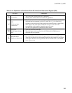
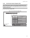
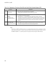
Table 13.4-2 Explanation of Functions of Each Bit in the Serial Rate Control Register (SRC)
Bit name Description
bit7,
bit6
Unused bits
• The values read out from these bits are undefined.
• Writing values to these bits does not affect any operations.
bit5
CR:
Clock rate input
selection bit
• This bit selects the clock rate in asynchronous transfer mode. However, when the
dedicated baud rate generator is used (CS1 and CS0 = 11
B
), it is fixed at 1/8
regardless of the value in the CR bit. Specifying an external clock or 8-bit PWM
timer output as the clock input, the baud rate is set to 1/16 or 1/64 of the
corresponding clock frequency, depending on the CR value.
• This bit is not significant in synchronous transfer mode.
bit4,
bit3
CS1,CS0:
Clock input selection
bits
• These bits select the clock input.
• The clock input can be an external clock (UCK pin), 8-bit PWM timer, or
dedicated baud rate generator.
bit2
to
bit0
RC2,RC1,RC0:
Baud rate selection bits
• There are 8 types of baud rate in asynchronous transfer mode and 6 types of baud
rate in synchronous transfer mode: 14 types of baud rate are selectable in total.
• These bits are effective only when the dedicated baud rate generator is used for the
clock input. These bits are not significant when an external clock or 8-bit PWM
timer output is used.