


197
CHAPTER 8 8/16-BIT CAPTURE TIMER/COUNTER
8.9 8/16-bit Capture Timer/Counter Operation in Each Mode
This section describes the operation of the 8/16-bit capture timer/counter when it
switches to the sleep or stop mode or when a halfway stop request is issued during the
operation of the interval timer or counter function.
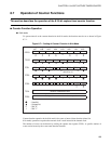
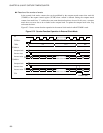
■ Operation in Standby Mode and at Halfway Stop
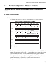
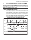
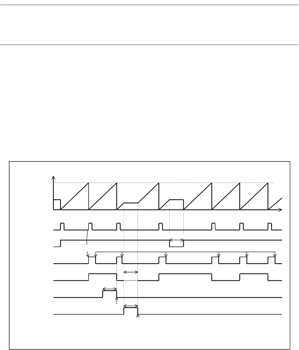
Figure 8.9-1 shows the counter value states if the 8/16-bit capture timer/counter switches to the sleep or
stop mode or when a halfway stop request is issued when the interval timer or counter function is in
operation (at timer 0 operation).
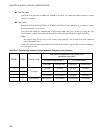
When the counter switches to the stop mode, it retains the value and stops. If the stop mode is released by
an external interrupt, the counter starts its operation at the retained value, and so the first interval time and
external clock count are incorrect. When the stop mode is released, the 8/16-bit capture timer/counter must
be initialized.
When the counter is temporarily stopped (TSTR0 = 0), it retains its value and stops. If the subsequent
operation is continued (TSTR0 = 1), the count value is cleared and the counter is restarted.
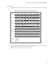
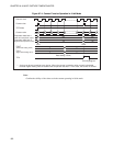
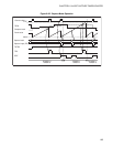
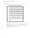
Figure 8.9-1 Counter Operation in Standby Mode and at Halfway Stop
0000
H
Counter value
Value set in data
register
Counter clear
Start
Match
Match
Match Match Match
Time
TSTR0 bit
Clear by program
Temporary stop
TIF0 bit
TO pin
Sleep
*
SLP bit
(STBC register)
Sleep release by IRQ3
Stop
STP bit
(STBC register)
External interrupt
*:
When the pin state specification bit (SPL) of the standby control register (STBC) is "1" and the TO pin is not
pulled up, the TO pin in the stop mode becomes Hi-Z. When the pin sta
te specification bit (SPL) is "0", the value
immediately before the 8/16-bit capture timer/counter switches to the stop mode is retained.