


320
CHAPTER 14 8-BIT SERIAL I/O
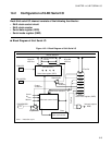
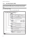
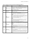
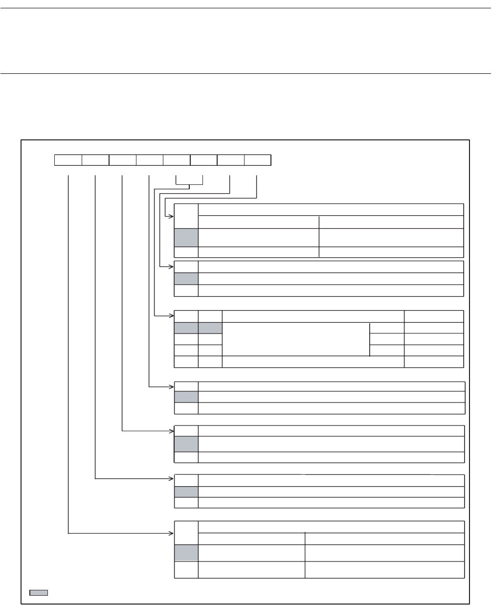
14.4.1 Serial Mode Register (SMR)
The serial mode register (SMR) is used to allow and prohibit 8-bit serial I/O operation,
select a shift clock, set a transfer direction, control interrupts, and check interrupt
states.
■ Serial Mode Register (SMR)
Figure 14.4-2 Serial Mode Register (SMR)
SST
0
BDS
0
1
CKS1CKS0
00
2 t
INST
01
8 t
INST
1 0 32 t
INST
11
SOE
0
SCKE
0
SIOE
0
SIOF
0
bit7 bit6 bit5 bit4 bit3 bit2 bit1 bit0
0039
H
SIOF SIOE
SCKE SOE
CKS1
CKS0 BDS
SST 00000000
B
R/W R/W R/W R/W R/W R/W R/W R/W
R/W : Readable and Writable
: Initial value
t
INST
: Instruction cycle
1
1
1
1
1
Address
Initial value
Serial I/O transfer start bit
At read At write
Serial I/O transfer is stopped.
Serial I/O transfer is stopped or
prohibited.
Serial I/O transfer is in progress.
Serial I/O transfer is started or allowed.
Transfer direction selection bit
LSB first (serial I/O transfer starts at the lowest bit.)
MSB first (serial I/O transfer starts at the highest bit.)
Shift clock selection bits
SCK pin
Internal shift clock
External shift clock
Output
Output
Output
Input
Serial data output allowance bit
P31/UO/SO is used as a general-purpose port (P31).
P31/UO/SO is used as a serial data output pin.
Shift clock output allowance bit
P30/UCK/SCK is used as a general-purpose port (P30) or the shift
clock input pin (SCK).
P30/UCK/SCK is used as the shift clock output pin.
Interrupt request allowance bit
Interrupt request output is prohibited.
Interrupt request output is allowed.
Interrupt request flag bit
At read At write
Serial transfer has not
terminated.
This bit is cleared.
Serial transfer has already
terminated.
Remains unchanged. This bit does not
affect other bits.