


159
CHAPTER 7 8-BIT PWM TIMER
■
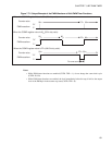
Program Example of PWM Timer Functions
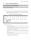
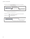
● Processing specifications
• A PWM wave with a duty ratio of 50% is generated. The duty ratio is then changed to 25%.
• No interrupt occurs.
• When the count clock is 16 t
INST
of an internal count clock, the cycle of the PWM wave is 16 × 4/12.5
MHz × 256 = 1.3107 ms, which occurs when the top speed of the gear (one instruction cycle = 4/F
CH
) is
obtained at an oscillation frequency of 12.5 MHz.
• The COMR register value with a duty ratio of 50% is shown below.
COMR register value = 50/100 × 256 = 128 (080
H
)
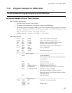
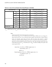
● Coding example
CNTR EQU 0022H ; Address of the PWM control register
COMR EQU 0023H ; Address of the PWM compare register
TPE EQU CNTR:3 ; Defining the bit to enable the counter operation
;------------------------Main program---------------------------------------------------------------------------------
CSEG ; [CODE SEGMENT]
:
CLRB TPE ; Stopping the counter operation
MOV COMR,#80H ; Specification of the H-level width of a pulse, 50% duty
ratio
MOV CNTR,#10011010B ; PWM timer operation, selection of 16 t
INST
; Starting the counter operation, clearing the interrupt
request flag
; Enabling the output of the PWM pin, disabling the output
of interrupt requests
:
:
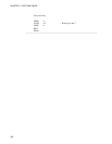
MOV COMR,#40H ; Changing the duty ratio to 25% (Takes effect at the next
cycle of the PWM wave.)
:
ENDS
;---------------------------------------------------------------------------------------------------------------------
END