


140
CHAPTER 7 8-BIT PWM TIMER
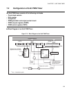
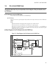
● Count clock selector
The count clock selector selects one of three types of internal counter clock. The selector also selects an 8/
16-bit capture timer or counter and uses it to increment the count of the 8-bit counter.
● 8-bit counter
This counter is incremented by the count clock selected by the count clock selector.
● Comparator
A latch in the comparator holds the COMR register value when the value of the 8-bit counter is 00
H
and
then compares the 8-bit counter with the COMR register value latched and detects a match.
● PWM generation circuit and PWM output control circuit
During the interval timer operation, once a match is detected, an interrupt request occurs. And when the bit
to control the output pin (CNTR: OE) is "1", the output level of the P50/PWM pin is inverted by the output
control circuit, at which time the 8-bit counter is cleared.
During the PWM timer operation, once a match is detected, the output level of the P50/PWM pin is
changed from "H" level to "L" level by the PWM generation circuit. Thereafter, when the 8-bit counter
overflows, the output level is returned to "H" level.
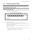
● COMR register
This register is used to set a value for comparison with the counter value of the 8-bit counter.
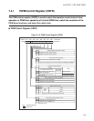
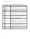
● CNTR register
This register is used to select the operation mode, enable and disable operations, set the count clock, control
interrupts, and check status.
When the operation mode is the PWM timer mode (P/TX = 0), the 8-bit counter cannot be cleared (by the
match detection signal from the comparator) and the interrupt request (IRQ9) is disabled.