


137
CHAPTER 7 8-BIT PWM TIMER
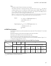
Note:
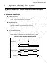
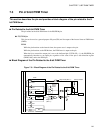
Calculation example of intervals and square wave frequency
The following expression is the interval when the count clock cycle is set to 1 t
INST
and when an
oscillation frequency (F
CH
) of 12.5 MHz and a PWM compare register (COMR) value of DD
H
(221)
are set. Another expression is the frequency of the square wave output from the PWM pin that is
operated continuously without changing the COMR register value.
However, the values are true when the maximum speed clock of the normal mode is selected (CS1,
CS0 = 11
B
, 1 instruction cycle = 4/F
CH
) with the system clock control register (SYCC).
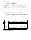
■
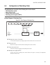
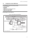
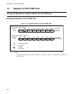
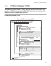
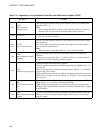
PWM Timer Functions
The PWM timer functions have an 8-bit resolution and can control the "H" level width and "L" level width
of one cycle.
Because the resolution is 1/256, a pulse can be output at a duty ratio of 0 to 99.6%.
The frequency of the PWM wave can be selected from four types.
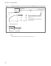
The low-pass filter can be connected to the output and used as the D/A converter.
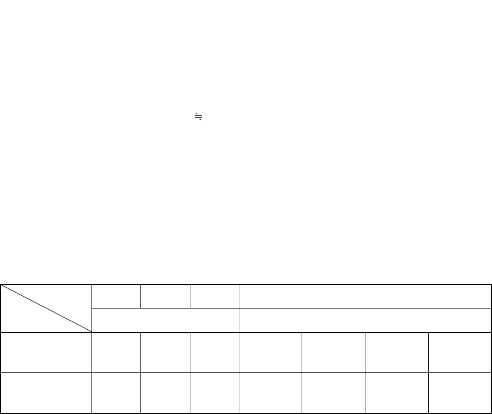
Table 7.1-2 shows the frequency of the PWM wave that can be set by PWM timer functions. Figure 7.1-1 is
a configuration example of the D/A converter.
= (1 × 4/F
CH
) × (COMR register value + 1)
= (4/12.5 MHz) × (221 + 1)
= 71.0 µs
Output frequency = F
CH
/ (1 × 8 × (COMR register value + 1))
= 12.5 MHz/ (8 × (221 + 1))
7.04 kHz
Interval
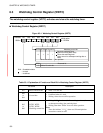
Table 7.1-2 Frequencies of the PWM Wave that can be Set by the PWM Timer Functions
123 4
Internal clock Output of an 8/16-bit capture timer/counter
Count clock cycle
1t
INST
16t
INST
64t
INST
2
2
t
INST
to
2
10
t
INST
2
6
t
INST
to
2
14
t
INST
2
10
t
INST
to
2
18
t
INST
1t
EXT
to
2
8
t
EXT
PWM wave cycle
2
8
t
INST
2
12
t
INST
2
14
t
INST
2
10
t
INST
to
2
18
t
INST
2
14
t
INST
to
2
22
t
INST
2
18
t
INST
to
2
26
t
INST
2
8
t
EXT
to
2
16
t
EXT
t
INST
: Instruction cycle (Affected by the clock mode and others.)
t
EXT
: Output frequency of an 8/16-bit capture timer