


275
CHAPTER 12 A/D CONVERTER
12.7 Notes on Using A/D Converter
This section describes notes on using the A/D converter.
■ Notes on Using the A/D Converter
● Input impedance of the analog input
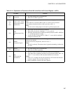
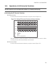
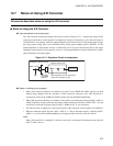
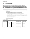
The A/D converter contains the sample hold circuit as shown in Figure 12.7-1 , captures the voltage of the
analog input, and holds it in the capacitor for sample hold in about 16 instruction cycles, after activation of
A/D conversion. Accordingly, when the output impedance of the external circuit of the analog input is high,
the analog input voltage may not be stabilized during analog input sampling period. Therefore, set the
output impedance of the external circuit to a sufficiently low level (lower than about 4 kΩ). If the output
impedance of the external circuit cannot be set low, it is recommended that a capacitor with about 0.1 µF be
added externally to the analog input.
Figure 12.7-1 Equivalent Circuit of Analog Input
● Notes on setting using a program
• When A/D conversion functions are enabled, the values in the ADDH and ADDL registers are held
without being changed until the activation of A/D conversion. However, once A/D conversion is
activated, the values in the ADDH and ADDL registers become undefined immediately.
• When A/D conversion functions are enabled, do not reselect an analog input channel (ADC1: ANS3 to
ANS0). Especially, during continuous activation, disable continuous activation (ADC2: EXT = 0), and
wait for the conversion in-progress flag bit (ADC1: ADMV) to be "0" for reselection.
• The A/D converter is stopped via a reset and activation of the stop mode, and all registers are initialized.
• When the interrupt request flag bit (ADC1: ADI) is "1" and an interrupt request is enabled (ADC2:
ADIE = 1), recovery from interrupt handling is no longer possible. Be sure to clear the ADI bit.
Note:
When A/D conversion is completed, if the next conversion is reactivated, the interrupt request flag bit
(ADC1: ADI) is not set.
RC
MB89202/F202RA series
Sample hold circuit
AN0 to AN7
Converter
Selecting
an analog
channel
After activation of A/D conversion,
close 16 instruction cycles