


285
CHAPTER 13 UART
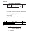
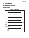
● Serial mode control register (SMC)
The SMC register controls UART operating mode. This register specifies the parity setting, stop bit length,
operating mode (data length), and synchronous/asynchronous mode, and enables/disables UART serial
clock output and serial data output.
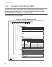
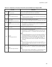
● Serial rate control register (SRC)
The SRC register controls the UART data transfer speed (baud rate). This register selects the input clock
and specifies the transfer rate to be applied when the baud rate generator is used.
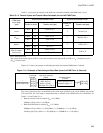
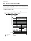
● Serial status and data register (SSD)
The SSD register indicates UART transmitting/receiving status, status in an error, parity received, or data
received at bit8. This register also enables/disables interrupts or specifies and confirms parity transmitted or
data transmitted with bit8.
● Serial input data register (SIDR)
The SIDR register stores received data. Serial input is converted, then stored into this register. However,
the most significant bit of 9-bit data is stored in the SSD RD8/RP bit.
● Serial output data register (SODR)
The SODR register specifies data to be transmitted. Data written into this register is converted to serial
format, then output. The most significant bit of 9-bit data is set in the SSD TD8/TP bit.
● Clock generator
The clock generator generates the transmit/receive clock in accordance with the dedicated baud rate
generator, external clock, and 8-bit PWM timer output.
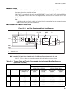
● Reception control circuit
The reception control circuit consists of the received byte counter, start bit detection circuit, and received
parity handling circuit.
The received byte counter takes count of received data. When a unit of data that corresponds to the
specified data length is fully received, an interrupt request is generated.
The start bit detection circuit detects start bits in serial input signals. When the start bit detection circuit
detects a start bit, it writes data into the SIDR with shifts in accordance with the transfer rate.
When parity is used, the received parity handling circuit stores the parity bit in the data received. It also
stores the most significant bit of 9-bit data received.
● Transmission control circuit
The transmission control circuit consists of the transmitted byte counter and transmitted parity handling
circuit.
The transmitted byte counter takes count of data to be transmitted. When a unit of data that corresponds to
the specified data length is fully transmitted, an interrupt request is generated.
When parity is used, the transmitted parity handling circuit generates a parity bit for the data to be
transmitted. It sets the most significant bit for data transmitted when it is made up of 9 bits.