


67
CHAPTER 3 CPU
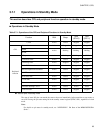
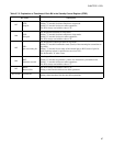
Table 3.7-2 Explanation of Functions of Each Bit in the Standby Control Register (STBC)
Bit name Description
bit7
STP:
Stop bit
This bit specifies transition to stop mode.
Writing "1" into this bit allows transition to stop mode.
Writing "0" into this bit does not affect operations.
This bit is always read with the value of "0".
bit6
SLP:
Sleep bit
This bit specifies transition to sleep mode.
Writing "1" into this bit allows transition to sleep mode.
Writing "0" into this bit does not affect operations.
This bit is always read with the value of "0".
bit5
SPL:
pin state setting bit
This bit specifies external pin states in stop mode.
Writing "0" into this bit maintains states (levels) of the external pins at transition to
stop mode.
Writing "1" into this bit sets states of the external pins to Hi-Z (states of pins for
which a pull-up resistor is specified are set to level "H").
This bit becomes "0" after a reset.
bit4
RST:
Software reset bit
This bit specifies software reset.
Writing "0" into this bit generates a source of 4-instruction cycle internal reset.
Writing "1" into this bit does not affect operations.
This bit is always read with the value of "1".
bit3
RESV:
Reserved bit
This bit is always read with the value of "0".
Writing a value into this bit does not affect operations.
bit2 to bit0 Unused bits
Values read out of these bits are undefined.
Writing values into these bits does not affect operations.