


173
CHAPTER 8 8/16-BIT CAPTURE TIMER/COUNTER
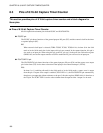
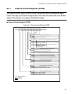
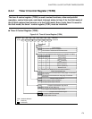
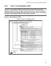
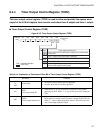
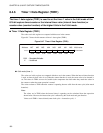
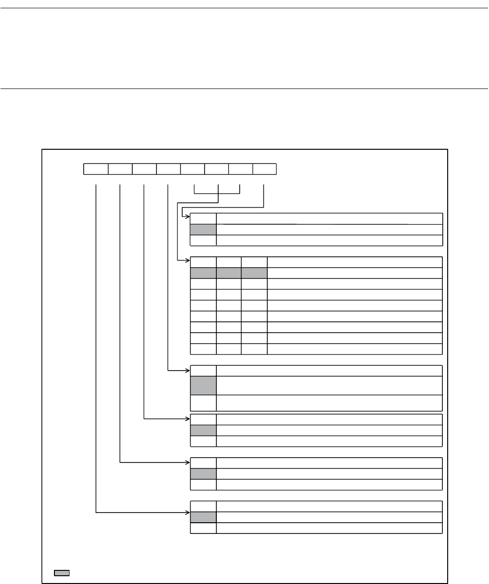
8.4.2 Timer 0 Control Register (TCR0)
The timer 0 control register (TCR0) is used to select functions, allow and prohibit
operation, control interrupts, and check interrupt states in timer 0 for the 8-bit mode of
the 8/16-bit capture timer/counter or in the 16-bit mode. Even if only timer 0 is used in
the 8-bit mode, the timer 1 control register (TCR1) must be initialized.
■ Timer 0 Control Register (TCR0)
Figure 8.4-3 Timer 0 Control Register (TCR0)
128t
INST
[40.96 µs]
16t
INST
[5.12 µs]
0
TCS02
TCS01 TCS00
00
0
001
01
0
011
100
1
0
1
110
111
CINV
0
1
T0IEN
0
1
TFCR0
0
TIF0
0
bit7 bit6 bit5 bit4 bit3bit2 bit1 bit0
TIF0 TFCR0 T0IEN CINV TCS02 TCS01
TCS00 TSTR0
R R/W R/W R/W R/W R/W R/W R/W
R/W: Readable/Writable
R : Read only
: Initial value
1
1
TSTR0
Address
Initial value
Timer start bit
The counter operation is stopped.
The counter is cleared and increment starts.
Clock source selection bits (oscillation: 12.5 MHz)
External clock
Count clock selection bit
The counter is incremented at the falling edge of a selected
clock source.
The counter is incremented at the rising edge of a selected
clock source.
Interrupt request enable bit
Interrupt request output is prohibited.
Interrupt request output is allowed.
Compare match detection flag clear bit
Not affected (at read, always "0")
The compare match detection flag is cleared.
Compare match detection flag
bit
No compare match has occurred.
A compare match occurred.
001B
H
00000000
B
2t
INST
[0.64 µs]
4t
INST
[1.28 µs]
64t
INST
[20.48 µs]
256t
INST
[81.92 µs]
512t
INST
[163.84 µs]
t
INST
: Instruction cycle (Affected by the clock mode and others.)
1