


314
CHAPTER 14 8-BIT SERIAL I/O
14.1 Overview of 8-Bit Serial I/O
The 8-bit serial I/O has a function that serially transfers 8-bit data in synchronization
with a shift clock. It can select one shift clock from three internal shift clocks and one
external shift clock. It can also select LSB first or MSB first as the data shift direction.
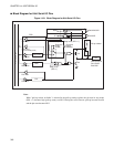
■ Serial I/O Function
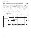
The 8-bit serial I/O function serially inputs and outputs 8-bit data in synchronization with a shift clock.
• Converts 8-bit parallel data to 8-bit serial data and outputs it. Also inputs 8-bit serial data, converts the
data to 8-bit parallel data, and stores it.
• Can select one shift clock from three internal shift clocks and one external shift clock.
• Can control shift clock input/output and output internal shift clocks.
• Can select LSB first or MSB first as the data shift direction.
■
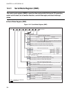
Serial Function Switching
The 8-bit serial I/O and UART cannot be used simultaneously because they use the same pin. For this
reason, the serial function switching circuit must be used to switch the 8-bit serial I/O and UART. For more
information on the serial function switching circuit, see Section "13.4.7 Serial Switch Register (SSEL) ".
Selecting the 8-bit serial I/O with this serial function switching circuit enables P30/UCK/SCK to be used as
the serial clock I/O pin (SCK) of the serial I/O, and P31/UO/SO to be used as the data output pin (SO). This
selection also enables P32/UI/SI to be used as the data input pin (SI).
Note:
This chapter describes pin function switching and the register function, etc., on the assumption that the 8-
bit serial I/O is selected with the serial function switching circuit.
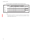
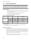
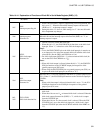
Table 14.1-1 Shift Clock Cycle and Transfer Rate
Shift clock Clock cycle Frequency (Hz)
Transfer rate
(F
CH
=12.5MHz, At maximum speed*)
Internal shift clock
(output)
2t
INST
1/ (2t
INST
)
1562.5 kbps
8t
INST
1/ (8t
INST
)
390.6 kbps
32t
INST
1/ (32t
INST
)
97.66 kbps
External shift clock
(input)
2t
INST
or lower 1/(2t
INST
) or lower
DC to 1562.5 kbps
F
CH
: Oscillation frequency
t
INST
: Instruction cycle
* : When the highest speed clock of a general mode is selected with the system clock control register (SYCC)
(CS1 and CS0 bits of SYCC = 11
B
, 1 instruction cycle = 4/F
CH
)