


164
CHAPTER 8 8/16-BIT CAPTURE TIMER/COUNTER
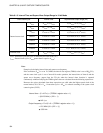
Note:
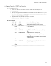
Example of calculating interval time and square wave frequency
If the oscillation (F
CH
) is set to 12.5 MHz, the timer 0 data register (TDR0) value is set to DD
H
(221),
and the count clock cycle is set to 2t
INST
8-bit mode operation, the interval time of timer 0 and the
square wave frequency output from the TO pin when the interval timer function is operated
continuously without modifying the TDR0 register value are calculated from the following expressions:
However, the values calculated from these expressions are valid when the highest speed clock of the
normal mode (CS1, CS0 = 11
B
, 1 instruction cycle = 4/F
CH
) is selected according to the system clock
control register (SYCC).
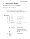
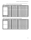
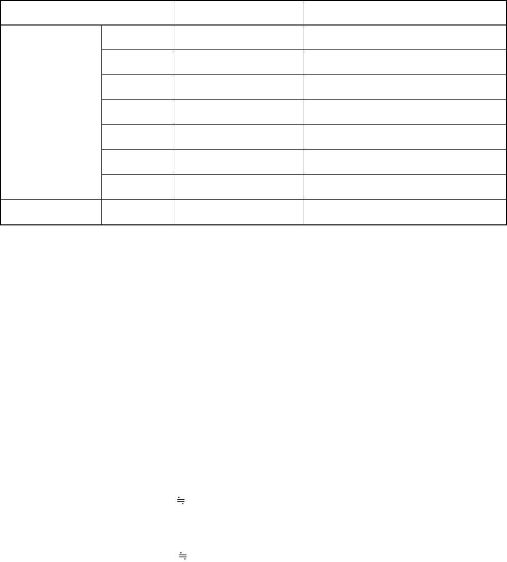
Table 8.1-3 Interval Time and Square Wave Output Range in 16-bit Mode
Count clock cycle Interval time Square wave output range (Hz)
Internal count clock
2t
INST
2t
INST
to 2
17
t
INST
1/ (2
2
t
INST
) to 1/ (2
18
t
INST
)
4t
INST
2
2
t
INST
to 2
18
t
INST
1/ (2
3
t
INST
) to 1/ (2
19
t
INST
)
16t
INST
2
4
t
INST
to 2
20
t
INST
1/ (2
5
t
INST
) to 1/ (2
21
t
INST
)
64t
INST
2
6
t
INST
to 2
22
t
INST
1/ (2
7
t
INST
) to 1/ (2
23
t
INST
)
128t
INST
2
7
t
INST
to 2
23
t
INST
1/ (2
8
t
INST
) to 1/ (2
24
t
INST
)
256t
INST
2
8
t
INST
to 2
24
t
INST
1/ (2
9
t
INST
) to 1/ (2
25
t
INST
)
512t
INST
2
9
t
INST
to 2
25
t
INST
1/ (2
10
t
INST
) to 1/ (2
26
t
INST
)
External clock
1t
EXT
1t
EXT
to 2
16
t
EXT
1/ (2t
EXT
) to 1/ (2
17
t
EXT
)
t
INST
: Instruction cycle (this cycle is affected by the clock mode, etc.)
t
EXT
: External clock cycle (1t
EXT
greater than or equal to 4t
INST
)
Interval time = (2 × 4/F
CH
) × (TDR0#1 register value + 1)
= (8/12.5 MHz) × (221 + 1)
142.1 µs
Output frequency = F
CH
/(2 × 8 × (TDR0#1 register value + 1))
= 12.5 MHz/(16 × (221 + 1))
3.53 kHz