274
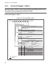
CHAPTER 12 A/D CONVERTER
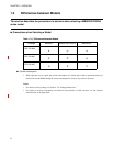
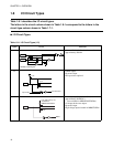
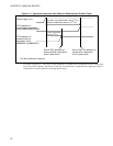
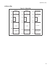
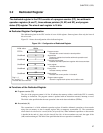
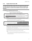
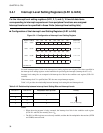
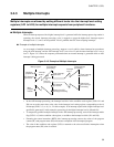
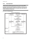
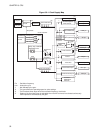
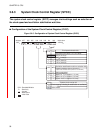
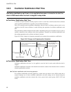
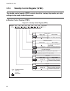
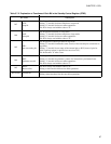
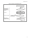
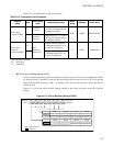
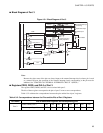
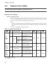
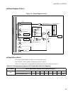
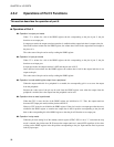
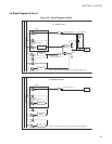
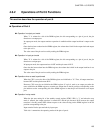
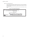
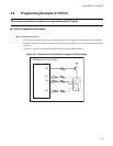
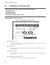
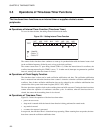
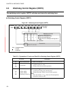
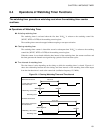
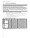
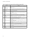
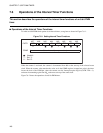
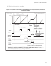
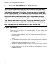
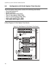
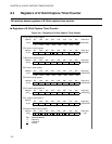
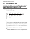
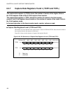
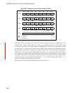
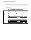
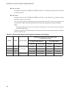
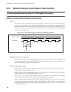
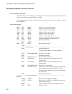
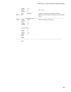
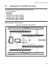
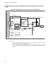
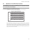
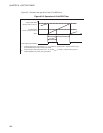
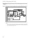
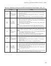
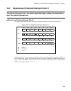
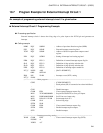
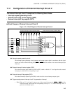
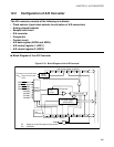
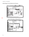
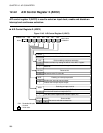
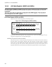
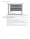
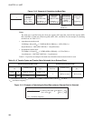
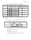
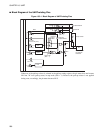
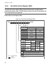
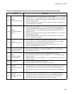
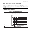
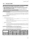
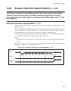
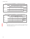
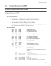
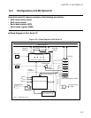
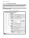
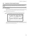
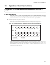
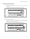
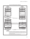
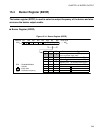
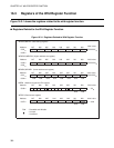
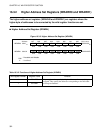
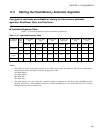
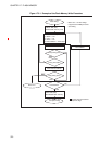
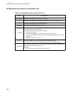
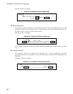
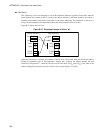
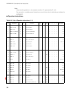
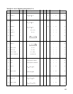
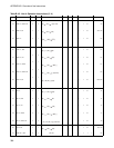
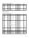
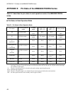
Figure 12.6-2 Setting A/D Conversion Functions (at Continuous Activation)
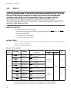
When continuous activation is enabled, A/D conversion is activated on a rising edge of the selected input
clock and the operations of A/D conversion functions are started. When continuous activation is disabled
(ADC2: EXT = 0), continuous activation is stopped and activation with software is possible.
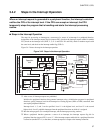
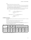
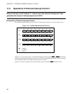
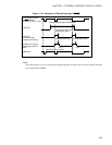
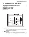
■
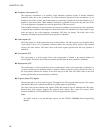
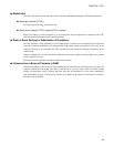
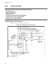
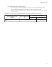
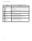
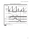
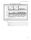
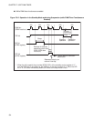
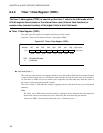
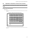
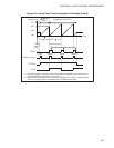
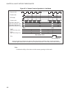
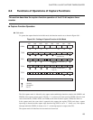
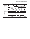
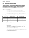
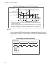
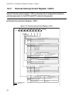
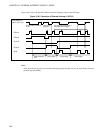
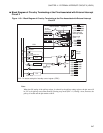
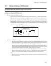
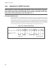
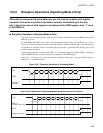
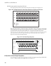
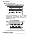
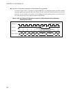
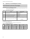
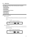
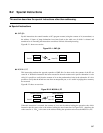
Operations of A/D Conversion Functions
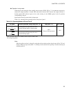
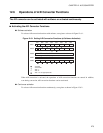
The operations of the A/D converter are described here. It takes about 38 instruction cycles from activating
A/D conversion to completing it.
1. When A/D conversion is activated, the conversion in-progress flag bit is set (ADC1: ADMV = 1), and
the analog input set is connected to the sample hold circuit.
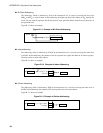
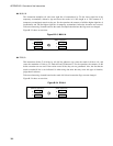
2. During about 16 instruction cycles, the voltage of the analog input is captured and held in the capacitor
for internal sample hold. This voltage is held until A/D conversion has been completed.
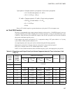
3. The comparator compares the voltage captured and held in the capacitor for sample hold with the
reference voltage for A/D conversion from the MSB to the LSB. The results are transferred to the
ADDH and ADDL registers in turn.
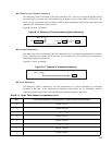
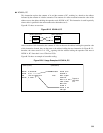
4. When all the results have been transferred to the ADDH and ADDL registers, the conversion in-
progress flag bit is cleared (ADC1: ADMV = 0), and the interrupt request flag bit is set (ADC1: ADI =
1).
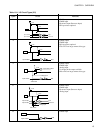
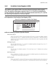
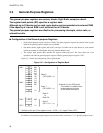
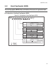
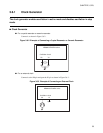
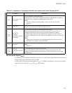
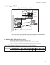
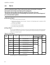
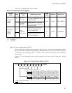
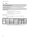
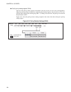
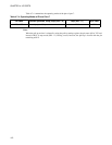
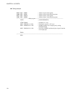
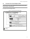
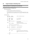
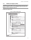
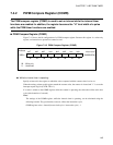
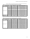
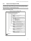
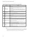
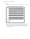
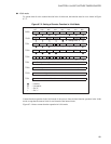
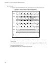
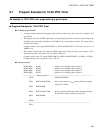
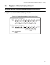
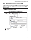
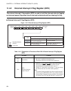
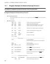
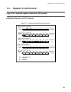
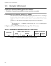
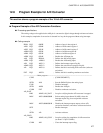
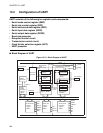
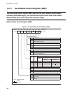
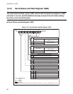
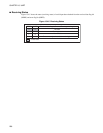
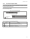
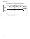
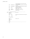
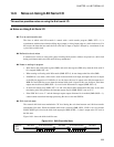
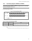
bit7 bit6 bit5 bit4 bit3 bit2 bit1 bit0
ADC1
ANS2 ANS1 ANS0 ADI ADMV
RESV0
AD
ADC2
RESV4 RESV3 ADCK
ADIE
RESV2
EXT
RESV1
00 011
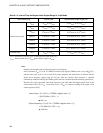
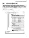
ADDH
ADDL
ADEN
: Used bit
: Unused bit
1 : Set "1"
0 : Set "0"
: Set "1" to an appropriate bit
The results of A/D conversion are stored.
The results of A/D conversion are stored.