


157
CHAPTER 7 8-BIT PWM TIMER
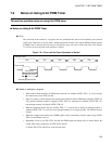
7.10 Program Example for PWM Timer
This section describes program examples of an 8-bit PWM timer.
■ Program Example of Interval Timer Functions
● Processing specifications
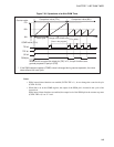
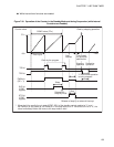
• 5 ms interval timer interrupts occur repeatedly.
• The square waveform that inverts at an interval is output to the P50/PWM pin.
• The following expression yields the COMR register value for which the interval is about 5 ms when the
top speed of the gear (one instruction cycle = 4/F
CH
) is obtained at an oscillation frequency of 12.5
MHz. The count clock is 64 t
INST
of the internal count clock.
COMR register value = 5 ms/(64 × 4/12.5 MHz) - 1 = 244.1 (0F4
H
)
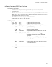
● Coding example
CNTR EQU 0022H ; Address of the PWM control register
COMR EQU 0023H ; Address of the PWM compare register
TPE EQU CNTR:3 ; Defining the bit to enable the counter operation
TIR EQU CNTR:2 ; Defining the interrupt request flag bit
ILR3 EQU 007D ; Address of the register to set the interrupt level
INT_V DSEG ABS ; [DATA SEGMENT]
ORG 0FFF8H
IRQ9 DW WARI1 ; Setting the interrupt vector
INT_V ENDS
;------------------------Main program---------------------------------------------------------------------------------
CSEG ; [CODE SEGMENT]
; The stack pointer (SP) and others are assumed to have
been initialized.
:
CLRI ; Disabling interrupts
CLRB TPE ; Stopping the counter operation
MOV ILR3,#11110111B ; Setting the interrupt level (level 1)
MOV COMR,#0F4H ; Comparison value with the counter value (interval)
MOV CNTR,#00101011B ; Enabling the output of the PWM
; Interval timer operation, selection of 64 t
INST
; Starting the counter operation and enabling the output
of interrupt requests
SETI ; Enabling interrupts
:
;------------------------Interrupt program----------------------------------------------------------------------------
WARI1 CLRB TIR ; Clearing the interrupt request flag
PUSHW A
XCHW A,T ; Saving A and T
PUSHW A