


176
CHAPTER 8 8/16-BIT CAPTURE TIMER/COUNTER
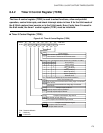
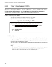
Note:
When using timer 1 in the 16-bit mode, write 111
B
to the TCS12, TCS11, and TCS10 bits and then
control timer 1 with TCR0.
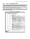
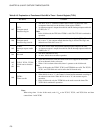
Table 8.4-3 Explanation of Functions of Each Bit in Timer 1 Control Register (TCR1)
Bit name Function
bit7
TIF1:
Compare match
detection flag bit
• This bit is set to "1" when the counter value of timer 1 matches the value
(comparator data latch) set in the timer 1 data register (TDR1).
• An interrupt request is output when this bit and the interrupt request enable bit
(T1IEN) are "1".
Note:
In the 16-bit mode, the TIF0 bit of TCR0 is valid. The TIF1 bit is unrelated to
operation.
bit6
TFCR1:
Compare match
detection flag clear bit
• This bit is used to clear the compare match detection flag bit (TIF1). When this
bit is set to "1", the compare match detection flag is cleared. The flag is not
affected even if this bit is set to "0".
bit5
T1IEN:
Interrupt request enable
bit
• This bit is used to allow and prohibit interrupt request output to the CPU.
• An interrupt request is output when this bit and the interrupt request enable bit
(T0IEN) are "1".
bit4 Not used
• This bit is undefined at read.
• At write, this bit does not affect operation.
bit3
to
bit1
TCS12, TCS11, TCS10:
Clock source selection
bits
• These bits are used to select the count clocks to be supplied to the counter.
• Of seven internal clocks, select one.
• When 111
B
is written to these bits, timer 1 operates as the 16-bit mode.
Note:
In the 16-bit mode, the TCS02, TCS01, and TCS00 bits are valid. The TCS12,
TCS11, and TCS10 bits are used to select the 16-bit mode only.
bit0
TSTR1:
Timer start bit
• This bit is used to start and stop the counter.
• When this bit is set to "1", the counter is cleared and incremented according to
the selected count clock. When this bit is set to "0", the counter stops its
operation.
• In the 16-bit mode, only the TSTR0 bit can be used to start the timer. The
TSTR1 bit is unrelated to operation.