


186
CHAPTER 8 8/16-BIT CAPTURE TIMER/COUNTER
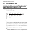
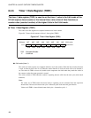
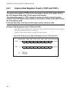
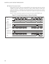
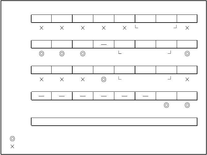
Figure 8.6-2 Setting of Interval Timer Function (Timer 1)
When the counter is activated in the 8-bit mode, increment begins at the rising or falling edge of the
selected clock, starting at 00
H
. When the counter value matches the value set in the data register
(comparator data latch), the interrupt request bit (TCR0: TIF0 or TCR1: TIF1) of the timer 0 control
register is set to "1" and the count operation is started at 00
H
. If the counter value matches the value set in
the data register when timer 0 is being used, the output of the square wave output control circuit toggles.
When square wave output is allowed (TCR2: PEN) and timer 0 is set to output selection (TCR2: TSEL =
0), a square wave is output from the timer output pin (TO). If the counter value matches the value set in the
data register when timer 1 is being used, the output of the square wave output control circuit toggles. When
square wave output is allowed (TCR2: PEN) and timer 1 is set to output selection (TCR2: TSEL = 1), a
square wave is output from the timer output pin (TO).
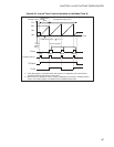
Figure 8.6-3 shows interval timer function operation in the 8-bit mode.
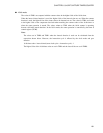
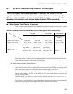
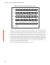
bit7 bit6 bit5 bit4 bit3 bit2 bit1 bit0
TCCR
CPIF
CFCLR CPIEN
CCMSK
TCMSK EDGS1
EDGS0 RESV
TCR1
TIF1
TFCR1
T1IEN
TCS12
TCS11
TCS10
TSTR1
TCR0
TIF0
TFCR0 T0IEN CINV TCS02 TCS01 TCS00
TSTR0
TCR2
PEN TSEL
TDR1
: Used bit
: Unused bit
Setting of 00
Setting of a value
other than 111
Setting of interval time
Setting of a value
other than 111