


148
CHAPTER 7 8-BIT PWM TIMER
7.6 Operations of the Interval Timer Functions
This section describes the operations of the interval timer functions of an 8-bit PWM
timer.
■ Operations of the Interval Timer Functions
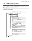
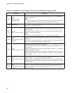
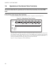
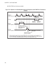
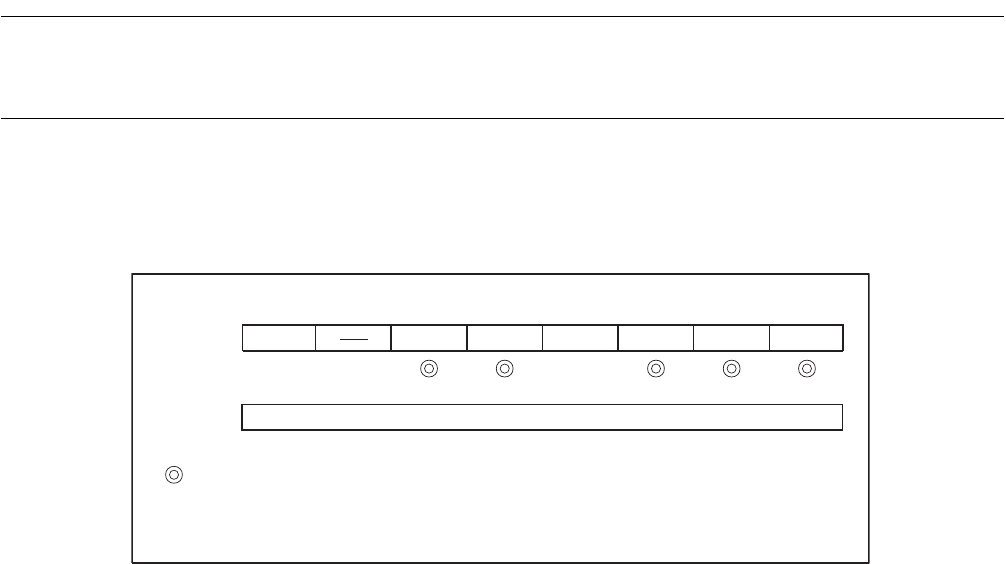
To make an 8-bit PWM timer operate as an interval timer, set registers as shown in Figure 7.6-1 .
Figure 7.6-1 Setting Interval Timer Functions
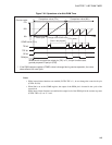
When the counter is activated, the counter is incremented from 00
H
at the start-up of the selected count
clock. When the counter value matches the value set in the COMR register (comparison value), the timer
inverts the level of the PWM pin, clears the counter, sets the interrupt request flag bit (CNTR: TIR = 1),
and starts incrementing again from 00
H
at the next start-up of the count clock.
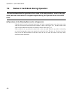
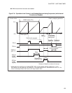
Figure 7.6-2 shows the operations of an 8-bit PWM timer.
bit7 bit6 bit5 bit4 bit3 bit2 bit1 bit0
CNTR P/TX P1 P0 TPE TIR OE TIE
0 1
COMR
1
0
Set an interval (compare value)
: Used bit
: Set "1".
: Set "0".