


295
CHAPTER 13 UART
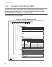
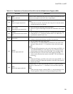
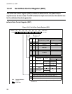
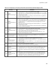
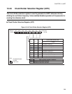
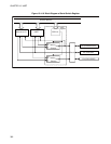
Table 13.4-3 Explanation of Functions of Each Bit in the Serial Status and Data Register (SSD)
Bit name Description
bit7
RDRF:
Received data flag bit
• This bit indicates the state of serial input data register (SIDR).
• When this bit is "1", reading the SSD register, then the SIDR register clears RDRF.
• When this bit and reception interrupt request enable bit (RIE) are "1", the reception
interrupt request is output.
• This bit is intended only for read. Writing a value into this bit has no significance
and does not affect any operation.
bit6
ORFE:
Overrun/Framing error
flag bit
• This bit indicates that the overrun or framing error occurs.
• When an error occurs (ORFE = 1), no data is transferred from the reception shift
register to the SIDR register. Therefore, when an error occurs, the RDRF bit is not
set. When this bit is "1", reading the SSD register then SIDR register clears the
ORFE bit with "0".
• When this bit and reception interrupt request enable bit (RIE) are "1", the reception
interrupt request is output.
• This bit is intended only for read. Writing a value into this bit has no significance
and does not affect any operation.
bit5
TDRE:
Transmitted data flag
bit
• This bit indicates the state of serial output data register (SODR).
• When this bit is "1", reading the SSD register and writing data into the SODR
register output the data to the serial data output pin (UO).
• When this bit and transmission interrupt request enable bit (TIE) are "1", the
transmission interrupt request is output.
bit4
TIE:
Transmission interrupt
request enable bit
• This bit enables or disables the transmission interrupt request to the CPU.
• When this bit and transmission data flag bit (TDRE) are "1", the transmission
interrupt request is output.
bit3
RIE:
Reception interrupt
request enable bit
• This bit enables or disables the reception interrupt request to the CPU.
• When this bit and reception data flag bit (RDRF) are "1", the reception interrupt
request is output.
• When this bit and error flag bit (ORFE) are "1", the reception interrupt request for
an error is output.
bit2 Unused bit
• The value read out from this bit is undefined.
• Writing a value into this bit does not affect any operations.
bit1
TD8/TP:
Bit-8 transmitting data/
parity bit
• When parity is not used and operating mode is 2 or 3 (the length of data to be
transmitted/received is 9), this bit is handled as bit8 in the SODR register. When
operating mode is not 2 or 3 and parity is not used, this bit is not significant.
• When parity is used, this bit selects even parity or odd parity for the transmitted
data.
bit0
RD8/RP:
Bit-8 receiving data/
parity bit
• When parity is not used and operating mode is 2 or 3 (the length of data to be
transmitted/received is 9), this bit is handled as bit8 in the SIDR register. When
operating mode is not 2 or 3 and parity is not used, this bit is not significant.
• When parity is used, this bit indicates the parity of received data.